
-DQG-c1Ek.png)
Technical Article
Marine Fuel Injector Testing and Overhaul Explained
Marine fuel injector overhaul restores correct sealing, controlled opening, atomisation, spray distribution and repeatable closing without dribbling or after-injection. Testing and acceptance criteria vary significantly between low-speed two-stroke fuel valves, medium-speed and four-stroke injectors, mechanically controlled systems and electronically controlled systems, so the exact engine, injector design and maker procedure must always be confirmed.
What does a marine fuel injector do?
A marine fuel injector, or fuel valve on many large low-speed two-stroke engines, delivers metered fuel into the combustion chamber in a controlled spray pattern at the required injection event. Its practical job is not simply to pass fuel; it must seal before injection, open in a controlled way, atomise the fuel, distribute the spray correctly for the combustion chamber, and close cleanly without dribbling.
Injector condition directly affects combustion quality, exhaust-gas temperature, smoke, fuel consumption, carbon deposits, piston-crown loading, liner condition and starting performance. A visually clean injector can still fail on leakage, opening behaviour or spray quality, which is why workshop bench testing is essential after overhaul.
Even on electronically controlled engines such as MAN B&W ME-C, electronic timing does not remove the importance of the physical fuel valve and nozzle condition. The control system may command the injection event correctly, but poor nozzle seating, blocked holes, internal leakage, sticking or poor atomisation can still create poor combustion.
Fuel injector versus fuel valve terminology
Large low-speed two-stroke engines commonly refer to the cylinder-mounted injection component as a fuel valve. Medium-speed and four-stroke main or auxiliary engines more commonly use the term fuel injector. This article uses both terms where appropriate.
The terminology should not make engineers assume the designs are identical. Nozzle-hole arrangement, needle or spindle design, spring or hydraulic closing method, cooling arrangement, pressure-control method, test procedure and acceptance criteria can differ greatly between makers and engine families.
Basic injector construction
Typical injector or fuel-valve assemblies may include an injector body, nozzle body, nozzle tip, needle or spindle, seating surface, spring or hydraulic closing arrangement where applicable, spindle guide, pressure pin or push rod where applicable, adjusting or shim arrangement, sealing faces, leak-off or return passages, cooling passages where fitted, and mounting threads or flanges.
Actual construction varies. Some components are matched precision assemblies, some designs use multiple fuel valves per cylinder, and some electronically controlled engines use upstream hydraulic or electronic control equipment to generate the injection event. The workshop should therefore identify the exact injector part number and configuration before dismantling or testing.
How a mechanical injector operates
In a conventional spring-loaded injector, rising fuel pressure acts on the needle or spindle and overcomes the closing force. The needle lifts, fuel flows through the nozzle holes, and the fuel is broken into a spray pattern inside the combustion chamber.
When injection pressure falls, the closing mechanism reseats the needle or spindle. Correct closing is as important as opening. If the seat leaks or the needle sticks, fuel can dribble after injection, carbonise at the tip, cause afterburning, raise exhaust temperature or produce smoke.
How injector operation differs on electronically controlled engines
On electronically controlled engines, the timing and generation of injection pressure may be controlled by electronic command, hydraulic actuation, pressure boosters, FIVA or ELFI arrangements where fitted, and cylinder-control logic. The physical fuel valve can still rely on fuel-pressure balance and clean nozzle/needle operation to produce the final spray.
For this reason, electronically controlled injection troubleshooting should connect the injector bench result with control-system evidence. A poor spray pattern may be a fuel-valve problem; a missing or late injection event may also involve FIVA, ELFI, HPS, pressure-booster or command/feedback issues depending on the engine design.
When should injectors be inspected or overhauled?
Injector inspection and overhaul may be required at maker-specified intervals, during scheduled engine overhaul, after abnormal cylinder performance, or when symptoms suggest poor injection quality. Actual overhaul intervals must come from the applicable engine and injector documentation.
Practical triggers include high exhaust-gas temperature, low exhaust-gas temperature on one unit, cylinder imbalance, smoke, afterburning, hard starting, failure to fire, poor combustion, abnormal fuel consumption, suspected nozzle leakage, carbon build-up, repeated injector alarms where applicable, abnormal leak-off or return behaviour, fuel contamination and poor indicator or cylinder-pressure evidence.
Pre-overhaul assessment
- Confirm engine model, injector type, part number and cylinder or unit location
- Record running hours, previous overhaul history and nozzle replacement history
- Review previous injector test results and any recurring defects
- Compare cylinder exhaust-temperature trends and power balance
- Review indicator diagrams or cylinder-pressure data where available
- Record smoke observations, fuel type, viscosity and temperature history
- Check contamination history, filter issues, water ingress or abrasive contamination concerns
- Review related injection-control alarms on electronically controlled engines
Removal and component identification
Before removal, engineers should confirm the correct cylinder, preserve component identity and protect high-pressure fuel connections from contamination. Fuel systems can retain dangerous pressure, so depressurisation, isolation and removal must follow maker and vessel procedures.
The workshop should keep injector bodies, nozzles, needles, springs, shims, pressure pins, cooling parts and seals identified according to the maker instructions. Mixing precision components can turn a repairable injector into an unreliable one.
Cleanliness and matched components
Marine injector internals operate with fine clearances and precision seating surfaces. Dirt, lint, metallic particles, hard carbon, water or unsuitable cleaning residue can cause sticking, leakage, abrasive wear or poor bench-test repeatability.
Matched nozzle and needle or spindle assemblies, where specified, must be kept together. These parts may be selected or matched during manufacture and should not be swapped between injectors unless maker documentation permits it.
Initial visual inspection
Initial inspection should look for carbon deposits, external leakage evidence, heat marks, erosion, corrosion, damaged mounting or sealing faces, damaged threads, nozzle-tip burning, cracks, impact marks, abnormal deposits and signs that the injector has been overheating or leaking.
Visual findings should be recorded before cleaning when they may help root-cause diagnosis. Heavy carbon on one nozzle tip, for example, may point to seat leakage, poor atomisation, cooling problems where applicable, incorrect fuel condition or poor combustion in that cylinder.
Nozzle inspection
Nozzle inspection should cover nozzle-hole condition, carbon blockage, erosion, cavitation-related damage where relevant, cracking, tip burning, deformation and deposit patterns. Partially blocked holes can produce missing jets, poor atomisation and uneven flame distribution.
Eroded or damaged nozzle holes can increase or distort fuel delivery and alter the intended spray. Nozzle-hole sizes, angles and acceptance limits are design-specific and must not be guessed or corrected with unsuitable tools.
Needle or spindle inspection
The needle or spindle should be checked for seating damage, guide-area scoring, sticking, wear, corrosion, heat damage and free movement according to the maker procedure. A sticky or worn needle can delay opening, delay closing, leak past the seat or produce inconsistent spray behaviour.
Free movement does not by itself prove the injector is acceptable. The seat must seal, the guide must control movement correctly, and the assembled injector must pass the applicable leakage and spray tests.
Needle and nozzle seating condition
A sound seating line is critical for shut-off. Leakage past the seat can allow dribbling, afterburning, carbon formation, smoke and high exhaust temperature. Seat leakage can also make the nozzle tip appear heavily carboned even when upstream fuel pressure and timing are correct.
Maker-approved lapping or seating restoration may be allowed on some designs, but not every nozzle or needle assembly can be re-lapped or reused. Unauthorised lapping, polishing or grinding can damage geometry and compromise injection quality.
Spring and closing mechanism inspection
Where spring-loaded injectors are used, spring condition, corrosion, fracture, loss of force, shim condition and adjuster condition influence opening behaviour and closing. The opening setting must be checked using the correct test method for the injector design.
Some fuel valves use hydraulic closing or other arrangements rather than a simple conventional spring test. Those designs must be assessed by their own maker-approved procedure rather than forced into a generic injector-test routine.
Body, spindle guide and internal passages
The body, spindle guide and internal passages should be inspected for wear, erosion, scoring, blocked passages, damaged leak-off or return paths, body cracking, distorted sealing faces and corrosion. Internal damage may show up as excessive leak-off, unstable opening behaviour or poor repeatability.
Blocked fuel passages can reduce or distort spray delivery. Blocked leak-off or return passages can affect injector operation or hide internal leakage symptoms depending on the design.
Cooling arrangement inspection where fitted
Some large two-stroke fuel valves include cooling arrangements. Inspection should cover passage cleanliness, leakage, sealing, blockage and evidence of overheating or deposit formation. Many injectors do not share the same cooling arrangement, so the workshop should not assume one design from another.
Where inadequate cooling is suspected, engineers should check the injector together with cooling supply, return, seals and combustion-chamber deposit evidence according to the engine documentation.
Injector test-bench operating principle
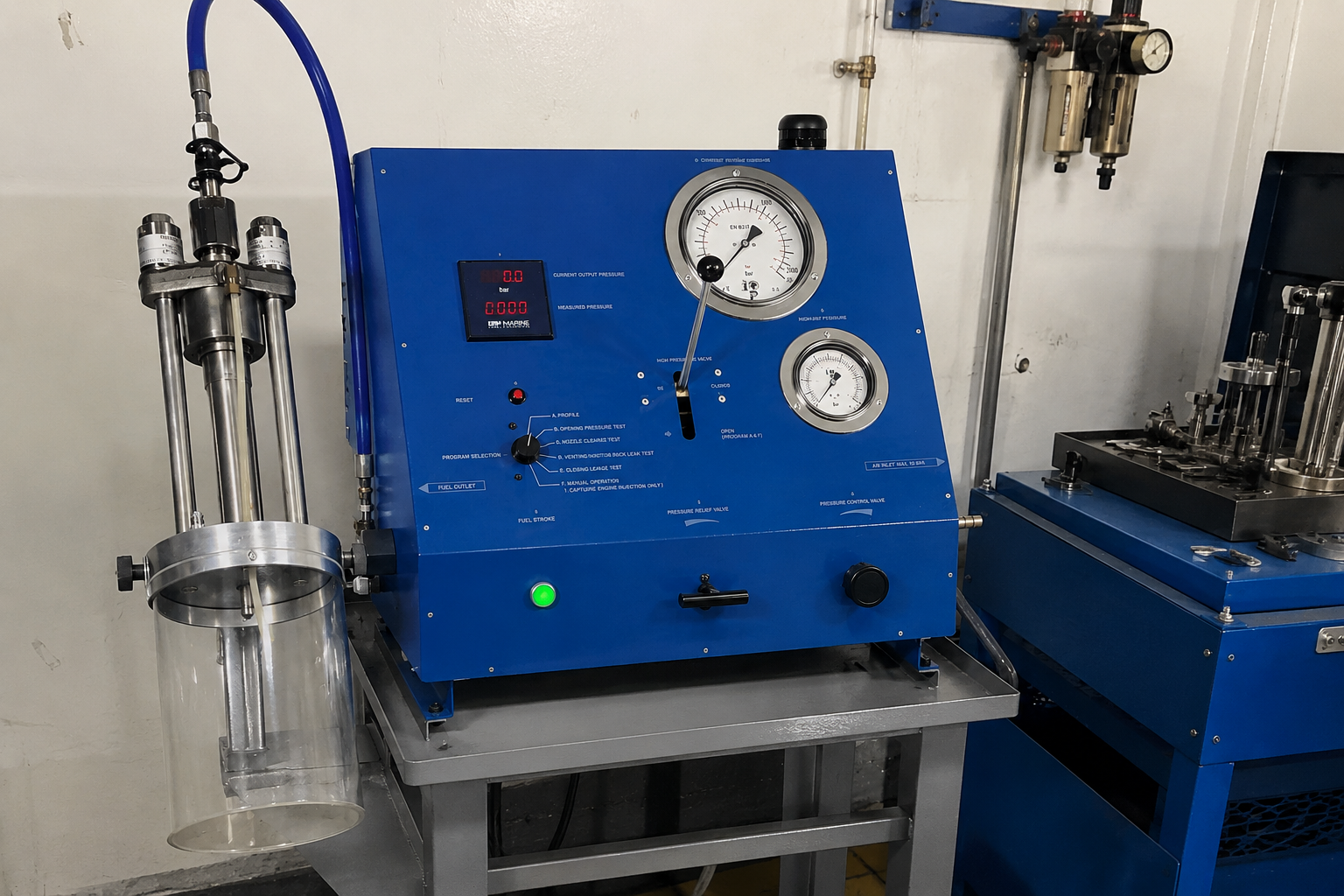
Marine fuel injector testing uses maker-approved test equipment to apply controlled fuel or approved test fluid so engineers can assess opening behaviour, seat leakage, spray pattern, atomisation, repeatability and injector-specific functions. The equipment must provide safe containment of high-pressure spray and leakage.
Test fluid, cleanliness, air removal, gauge condition, adapter condition and workshop procedure matter. A poor test result can come from the injector, but it can also come from contaminated test fluid, air in the test circuit, worn test equipment or incorrect setup.
Opening pressure or opening behaviour test
For suitable spring-loaded injectors, the opening test confirms whether the injector starts injection at the required maker-specified condition and whether the opening action is clean and repeatable. Incorrect opening behaviour can indicate spring setting problems, wear, internal leakage, sticking, contamination or component mismatch.
Some electronically controlled or hydraulically actuated fuel valves may not use the same conventional spring-loaded opening-pressure test method. Their functional test must follow the applicable fuel-valve or engine-control documentation.
Seat leakage test
A seat leakage test assesses whether the needle or spindle seals properly before and after injection. Dribbling, wetting at the nozzle tip or leakage outside maker criteria can indicate damaged seating, contamination, sticking, erosion or incorrect assembly.
Leakage is not only a workshop defect. In service it can cause carbon build-up, afterburning, smoke, high exhaust temperature, piston-crown deposits and poor combustion stability.
Spray pattern and atomisation assessment
Spray assessment checks whether the nozzle produces the correct number and direction of jets for the design, even distribution, fine atomisation and clean cut-off. Abnormal signs include solid streams, missing jets, side leakage, poor mist formation, distorted pattern and obvious dribbling.
Spray angles, nozzle-hole counts and nozzle-hole dimensions are not universal. The engineer should judge spray quality against the exact nozzle design and approved workshop criteria.
Chatter and response where applicable
Some spring-loaded injectors show a characteristic rapid opening and closing response on a manual test bench. This is often described as chatter and can help indicate clean movement and response on suitable designs.
Chatter is not a universal acceptance test for every marine fuel injector or fuel valve. Some designs must be evaluated by different functional criteria, especially electronically controlled or hydraulically actuated arrangements.
Leak-off and return flow assessment where applicable
Leak-off or return flow can help identify internal leakage, worn guide areas, damaged sealing surfaces or abnormal bypass. Excessive internal leakage may reduce effective injection quality or indicate that precision parts are beyond reuse.
Return-flow limits and measurement methods are design-specific. They should be assessed using the maker's workshop procedure and calibrated equipment.
Repeatability and consistency
A good injector should respond consistently across repeated test cycles under controlled conditions. An intermittent injector may pass one stroke and fail the next because of contamination, sticking, marginal seating, air in the test circuit or unstable internal behaviour.
Repeatability matters because the engine experiences thousands of injection events during operation. A fuel injector that is unpredictable on the bench should not be treated as reliable simply because one observation looked acceptable.
Injector test interpretation
| Injector Test | What It Checks | Possible Abnormal Finding | Possible Significance |
|---|---|---|---|
| Visual inspection | External condition before detailed overhaul | Carbon, heat marks, cracks, damaged threads or sealing faces | Leakage, overheating, incorrect installation or component damage |
| Nozzle-hole inspection | Condition of fuel discharge holes | Blocked, eroded, cracked or distorted holes | Poor spray distribution, over-fuelling, under-fuelling or poor atomisation |
| Seat leakage | Needle or spindle shut-off | Dribbling, wet tip or leakage outside criteria | Poor seating, contamination, erosion or sticking |
| Opening behaviour | Start of injection and response on suitable designs | Early, late, unstable or no opening | Spring issue, wear, sticking, internal leakage or wrong assembly |
| Spray pattern | Jet shape and direction | Missing jet, side spray or distorted pattern | Blocked/eroded nozzle hole or damaged tip |
| Atomisation | Fuel break-up quality | Solid stream or coarse spray | Poor combustion, smoke and deposits |
| Chatter/response where applicable | Rapid opening and closing behaviour | Weak, absent or irregular response | Sticking, air in test rig or unsuitable test method |
| Leak-off/return where applicable | Internal leakage path | Excessive or abnormal return | Wear, bypass, damaged guide or seal issue |
| Cooling integrity where applicable | Cooling passage sealing and flow path | Leakage, blockage or deposits | Overheating risk or cooling-system defect |
| Repeatability | Consistency over repeated cycles | Intermittent spray or leakage | Contamination, sticking, rig issue or marginal component condition |
Common injector faults and failure modes
Common injector faults include nozzle-hole blockage, nozzle erosion, poor atomisation, needle or spindle sticking, seat leakage, after-dribble, excessive internal leakage, weak or broken spring where fitted, incorrect adjustment, carbon build-up, contaminated fuel, corrosion, overheating, damaged body threads, damaged sealing faces and cooling leakage where applicable.
Each fault should trigger both component inspection and system thinking. For example, repeated nozzle-hole blockage may point to fuel cleanliness or poor combustion. Repeated erosion may point to abrasive contamination, fuel condition or abnormal operating environment. Repeated seat leakage after overhaul may point to poor cleaning, mismatched components, test-rig issues or incorrect reconditioning.
Symptom, possible cause and inspection
| Symptom | Possible cause | Inspection |
|---|---|---|
| High exhaust-gas temperature | Poor atomisation, dribbling, over-fuelling, exhaust-valve leakage, timing/control issue or overload | Test injector and compare exhaust valve, cylinder pressure, air supply and control data |
| Low exhaust-gas temperature on one unit | Low fuel delivery, blocked nozzle holes, injector not opening, upstream fuel issue or misfire | Check injector opening/spray, fuel supply and cylinder firing evidence |
| Black smoke | Poor atomisation, over-fuelling, air shortage, fuel quality issue or nozzle leakage | Inspect injector spray, air/scavenge condition, turbocharger and fuel condition |
| White or grey smoke | Poor ignition, low compression, cold cylinder, water/fuel issue or poor atomisation | Check injector, compression, starting condition and fuel quality |
| Afterburning | Dribbling, late combustion, poor atomisation, exhaust-valve issue or timing problem | Check seat leakage, spray pattern, exhaust valve and injection timing/control |
| Fuel knock | Timing issue, ignition delay, poor atomisation, fuel quality, compression or injector malfunction | Review timing/control, injector test, fuel condition and cylinder pressure |
| Hard starting | Injector not opening, poor spray, low fuel supply pressure, low compression or control fault | Confirm fuel reaches injector, test injector and verify starting/control systems |
| Failure to fire | Blocked nozzle, injector stuck closed, no upstream fuel pressure, control issue or compression problem | Check injection evidence, bench test, fuel pump/booster and compression |
| Rough running | Uneven injector performance, fuel delivery imbalance, control issue or mechanical cylinder defect | Compare cylinder data, injector test results and running condition |
| Cylinder power imbalance | Injector delivery/spray issue, timing/control issue, compression or exhaust-valve defect | Compare injector, indicator, exhaust valve and control data |
| High fuel consumption | Poor atomisation, leakage, incorrect combustion, overload or engine-condition issue | Check injectors with air supply, compression and operating load |
| Carboned nozzle tip | Seat leakage, poor atomisation, cooling issue where applicable or poor combustion | Inspect seat, spray, cooling and cylinder condition |
| Injector leakage | Seat damage, seal failure, cracked component, poor assembly or damaged fitting | Locate external/internal leakage and bench test |
| Repeated nozzle fouling | Fuel contamination, poor combustion, low temperature operation, leakage or wrong fuel conditioning | Investigate fuel treatment, combustion data and injector seating |
| Excessive leak-off | Guide wear, internal leakage, damaged precision parts or seal issue | Assess return flow by maker procedure and inspect internals |
| Poor spray pattern | Blocked/eroded holes, damaged nozzle tip, sticking needle or contaminated injector | Clean/inspect nozzle and repeat bench test |
| Recurring injector failure after overhaul | Fuel contamination, test-rig issue, mismatched parts, cooling problem or unresolved engine condition | Investigate root cause before repeated replacement |
High exhaust-temperature diagnosis
An injector can contribute to high exhaust-gas temperature through poor atomisation, dribbling, incorrect spray distribution, internal leakage or abnormal delivery. However, high exhaust temperature may also be caused by exhaust-valve leakage, compression problems, injection timing or control faults, overload, charge-air shortage, scavenge restriction or turbocharger problems.
A sound diagnosis compares exhaust-temperature trend, indicator data where available, smoke, fuel-valve bench results, exhaust-valve condition, compression evidence, fuel quality and control-system alarms before blaming one component.
Smoke and poor combustion diagnosis
Black smoke often points toward poor atomisation, over-fuelling, air shortage or poor fuel condition. White or grey smoke can be associated with poor ignition, low compression, cold operation, water contamination, fuel quality or incomplete combustion. Injector condition is one part of that picture.
Nozzle blockage, dribbling and poor atomisation can all produce deposits and smoke, but fuel temperature/viscosity, scavenge air, compression and cylinder mechanical condition should be checked at the same time.
Fuel knock diagnosis
Abnormal combustion noise can be related to injection timing, ignition delay, poor atomisation, fuel quality, compression condition or injector malfunction. It should not be reduced to one cause from sound alone.
Useful evidence includes recent fuel change, load condition, cylinder pressure data, injector bench test, timing/control status and whether the symptom follows the injector if components are swapped under an approved diagnostic plan.
Hard starting or failure-to-fire diagnosis
When a cylinder is hard to start or fails to fire, engineers should confirm whether fuel reaches the injector, whether the injector opens correctly, whether the nozzle is blocked, whether atomisation is acceptable, whether compression is adequate and whether upstream fuel or control systems are functioning.
On electronically controlled engines, missing injection may involve the control command, HPS, FIVA, ELFI, pressure booster or other upstream actuation equipment. The injector bench test proves the fuel valve condition, not the entire control system.
Root-cause investigation after repeated injector failure
Repeated nozzle or injector problems should trigger checks of fuel cleanliness, water contamination, catalytic fines or abrasive contamination where relevant, fuel temperature and viscosity control, filtration, upstream pump or pressure-booster condition, high-pressure pipe condition, combustion chamber condition and injector cooling where applicable.
Repeatedly changing injectors without addressing contaminated fuel, poor conditioning, test-rig problems or an engine-system fault can lead to recurrence. A useful workshop report should connect the component findings with operating history and fuel-system evidence.
Fuel quality and filtration relationship
Contaminated or poorly conditioned fuel can accelerate nozzle and needle wear, cause sticking, block nozzle holes, damage seating surfaces and produce deposits. Water, abrasive particles, unstable fuel blends and poor filtration can all affect injector life.
This article does not provide universal fuel-cleanliness thresholds. Fuel treatment and filtration standards must follow engine maker, fuel-equipment maker, vessel and fuel-management procedures.
Fuel temperature and viscosity relationship
Correct fuel conditioning matters because viscosity influences injection quality, leakage behaviour and lubrication of precision fuel-equipment surfaces. Fuel that is too poorly conditioned for the engine can contribute to poor atomisation, deposits, sticking or wear.
Actual fuel temperature, viscosity and changeover procedures are engine and fuel specific. They must be taken from the applicable engine and fuel-system documentation.
High-pressure fuel pipe and connection inspection
Injector faults should be assessed together with high-pressure fuel pipes, sealing surfaces, pipe supports, clamps, leak-off arrangements and protective jackets where applicable. Damaged connections, poor support or leakage can create unsafe conditions and misleading symptoms.
High-pressure fuel systems are hazardous. Inspection and leak checks must follow maker and vessel safety procedures and must not involve unsafe exposure to high-pressure spray.
Two-stroke versus four-stroke injector differences
Low-speed two-stroke engines often use larger fuel valves, may have multiple fuel valves per cylinder, and may include different cooling, mounting and nozzle arrangements. Medium-speed and four-stroke engines commonly use smaller injectors with design-specific spring, nozzle and return arrangements.
Testing methods can differ between main-engine fuel valves, auxiliary-engine injectors and electronically controlled systems. The workshop should not apply a four-stroke injector habit to a two-stroke fuel valve without verifying the procedure.
Mechanically controlled versus electronically controlled injection
Injector bench condition remains important in both mechanically and electronically controlled engines. A mechanically timed pump can deliver fuel at the correct time to a poor injector, and an electronic control system can command the correct injection event to a worn or leaking fuel valve.
On electronically controlled engines, engineers should also consider control command, HPS, FIVA, ELFI, pressure-booster and feedback status where applicable. On mechanically controlled engines, timing, fuel pump calibration, cam or actuator condition and linkage condition may be more central to the diagnosis.
Inspection and overhaul sequence
- Pre-clean and record external condition before removing useful evidence
- Dismantle under controlled workshop cleanliness using design-specific procedure
- Segregate and identify matched components, shims, springs and small parts
- Clean parts using approved methods without damaging precision surfaces
- Inspect nozzle, needle/spindle, seating, guide areas, body, passages and seals
- Measure only where maker documentation specifies a relevant measurement
- Renew or recondition components according to approved criteria
- Reassemble with correct matched parts, orientation, seals and controlled tightening
- Bench test after overhaul and record final results before release
Cleaning methods and contamination control
Nozzle holes and precision surfaces must be cleaned only with maker-approved tools and methods. Unsuitable abrasives, hard scraping, wire forcing or careless handling can enlarge nozzle holes, scratch matched surfaces, damage seating and ruin spray quality.
After cleaning, parts should be protected from dust, lint and moisture until assembly. Clean test fluid and clean bench equipment are part of the overhaul, not an optional extra.
Reconditioning versus renewal
Some components may be cleaned, reconditioned or re-lapped according to approved workshop procedures. Other parts, especially cracked nozzles, heavily eroded tips, worn matched nozzle/needle assemblies or damaged bodies, may require renewal.
Reuse decisions should be based on maker criteria, bench-test results, leakage behaviour, spray quality, wear, damage and operating history rather than visual appearance alone.
Key measurements and checks
Injector assessment may include nozzle and needle condition, spring condition or force where specified, opening behaviour, leak-off, nozzle protrusion or mounting dimensions where applicable, body and sealing condition, cooling integrity where fitted, and maker-specific internal measurements.
Many injector decisions are based on functional bench testing as much as dimensional inspection. Do not invent opening pressures, leakage limits, spring settings, nozzle-hole dimensions, spray angles, torques or renewal limits.
Component inspection and possible action
| Component/Area | Inspection/Measurement | Why It Matters | Possible Action |
|---|---|---|---|
| Nozzle tip | Burning, cracks, deformation, carbon and erosion | Affects spray and combustion chamber condition | Clean, inspect, test or renew by maker criteria |
| Nozzle holes | Blockage, erosion and deposit pattern | Controls jet distribution and atomisation | Approved cleaning or nozzle renewal |
| Needle/spindle | Seat, guide wear, scoring, corrosion and free movement | Controls opening, closing and leakage | Clean, inspect matched fit or renew assembly |
| Seat | Seating line and leakage evidence | Provides shut-off before and after injection | Approved restoration or renewal |
| Guide area | Wear, scoring, sticking and internal leakage signs | Controls movement and leak-off | Inspect, test leak-off or renew parts |
| Spring/closing mechanism | Spring damage, shim/adjuster condition or hydraulic closing function | Influences opening and closing behaviour | Set/test by maker procedure or renew |
| Body | Cracks, erosion, corrosion and sealing face damage | Maintains pressure integrity and alignment | Repair only if approved or renew |
| Leak-off passages | Blockage, abnormal deposits or leakage path | Shows internal leakage and permits correct return | Clean and verify by procedure |
| Cooling passages where applicable | Blockage, leakage, deposits and seal condition | Prevents overheating on relevant designs | Clean, pressure-test or repair by maker criteria |
| Sealing faces and threads | Damage, fretting, corrosion and fit | Prevents fuel/cooling leakage and poor mounting | Restore if permitted or renew affected parts |
Bench test interpretation
One abnormal spray or opening result should be repeated after confirming test-rig condition, cleanliness, correct adapters and absence of air in the test circuit. The bench result is only as reliable as the equipment and setup.
If the injector repeatedly fails after correct setup, the fault should be recorded with the observed symptom, component condition and suspected cause. That record helps the vessel distinguish component failure from fuel-system or engine-condition problems.
Test-rig condition and calibration
Faulty gauges, contaminated test fluid, air in the test circuit, worn hand pumps, damaged adapters or poor containment can produce misleading marine injector bench test results. Workshop test equipment must be maintained and calibrated according to workshop procedures.
The test bench should not be treated as a universal truth machine. It must be appropriate for the injector type, pressure range, test method and fluid specified by the maker.
Reassembly
Reassembly requires extreme cleanliness, correct matched-component pairing, correct orientation, maker-specified new seals where required, approved lubrication where applicable and controlled tightening according to the exact injector procedure.
Universal torques are not provided because injector body, nozzle holder, cap nut, mounting and connection requirements vary by design. Incorrect tightening can distort parts, damage threads, cause leakage or alter injector response.
Final bench test after overhaul
Every overhauled injector should be verified against the applicable maker-approved functional criteria before release for service. Final testing should confirm leakage condition, opening behaviour, spray pattern, atomisation, repeatability and any injector-specific checks.
The final report should identify the injector, cylinder assignment where known, parts renewed, test result, date and workshop technician or service engineer responsible according to local quality procedures.
Installation on engine
Installation should confirm clean seating surfaces, correct injector identity and orientation, correct sealing components, fuel/cooling/leak-off connections where applicable, and controlled tightening according to maker instructions.
After installation, fuel and cooling connections should be inspected under approved safe conditions. Protective arrangements around high-pressure fuel pipes and leak-off systems should be restored before operation.
Post-installation monitoring
During controlled operation, engineers should monitor leakage, exhaust-gas temperature comparison, smoke, combustion quality, cylinder balance, fuel consumption trend and alarm or performance data. A newly overhauled injector should improve the fault it was meant to address; if not, the root cause may be elsewhere.
Post-overhaul verification is especially important when the original complaint was intermittent, such as occasional smoke, variable cylinder output or recurring nozzle fouling.
What engineers should check before condemning an injector
- Cylinder performance trend and exhaust-temperature comparison
- Fuel supply condition, filtration and contamination history
- Fuel temperature and viscosity control
- Injection timing or electronic control status where applicable
- HPS, FIVA, ELFI or pressure-booster condition on applicable engines
- Compression and cylinder-pressure data where available
- Exhaust-valve condition, scavenge air and turbocharger performance
- High-pressure pipe, connection and leak-off condition
- Repeatable injector bench-test evidence
Injector fault versus control-system fault
| Observed Symptom | Injector Possibility | Control/Hydraulic Possibility | Mechanical Cylinder Possibility | Useful Checks |
|---|---|---|---|---|
| High exhaust temperature | Poor atomisation, dribbling or distorted spray | Timing command, FIVA/ELFI or booster issue | Exhaust-valve leakage, low compression or overload | Bench test, control data, indicator data and exhaust-valve inspection |
| Low cylinder output | Blocked nozzle or injector not opening correctly | Low actuation pressure or missing command | Compression loss or running-gear issue | Spray/opening test, HPS/control status and cylinder pressure |
| Smoke | Leakage, poor spray or carboned nozzle | Incorrect timing/quantity control | Air shortage or poor scavenging | Injector test, fuel condition and air path |
| Failure to fire | Stuck closed injector or blocked nozzle | No upstream injection command or pressure | Low compression | Fuel reaching injector, bench test and compression checks |
| Timing alarm on ME-C type engine | Fuel valve slow/leaking downstream | FIVA, ELFI, HPS, feedback or pressure-booster issue | Cylinder mechanical resistance | Alarm chronology, command/feedback, fuel valve and actuator checks |
| Recurring fouling | Seat leakage or poor atomisation | Incorrect control/timing or unstable pressure | Poor combustion chamber condition | Fuel quality, cooling, injector test and cylinder inspection |
FAQ
What is checked during a marine fuel injector overhaul?
Nozzle condition, needle or spindle seating, guide wear, carbon deposits, body condition, springs or closing mechanism, leakage, opening behaviour, spray pattern, atomisation, repeatability and any cooling or leak-off arrangements where applicable.
How is a marine injector tested?
It is tested on maker-approved equipment using suitable clean test fluid to assess leakage, opening behaviour, spray quality, atomisation and design-specific functions.
What does injector opening pressure mean?
On suitable spring-loaded injectors, it is the condition at which fuel pressure overcomes the closing force and the injector begins to open. Actual values are design-specific.
What causes poor spray pattern?
Blocked or eroded nozzle holes, damaged nozzle tips, sticking needles, contamination, poor assembly or worn precision parts can cause poor spray pattern.
What causes injector dribbling?
Common causes include poor seat sealing, contamination, erosion, sticking, incorrect assembly or damaged nozzle/needle components.
What causes black smoke from one cylinder?
Possible causes include poor atomisation, over-fuelling, nozzle leakage, air shortage, fuel quality problems or poor combustion in that cylinder.
What causes high exhaust temperature from an injector fault?
Poor atomisation, dribbling, distorted spray or abnormal fuel delivery can raise exhaust temperature, but exhaust-valve leakage, timing/control faults and air issues must also be checked.
What does injector chatter mean?
On some spring-loaded injectors it describes rapid opening and closing response on a test bench. It is not a universal acceptance test for every injector design.
Can every marine injector be tested the same way?
No. Two-stroke fuel valves, four-stroke injectors and electronically controlled fuel valves can require different test methods and acceptance criteria.
Why must nozzle and needle components be kept matched?
Matched precision components may be selected together for correct clearance, seating and movement. Mixing them can cause leakage, sticking or poor spray.
Can a nozzle be cleaned and reused?
Only if maker criteria allow it and the nozzle passes inspection and bench testing. Cracked, badly eroded or worn matched assemblies may require renewal.
When should a nozzle be renewed?
Renewal is normally required when damage, erosion, cracking, blocked or distorted holes, poor seating or failed bench tests exceed maker criteria.
What causes repeated injector fouling?
Fuel contamination, poor fuel conditioning, seat leakage, poor combustion, low-load operation, cooling issues where applicable or unresolved engine faults can contribute.
How does fuel contamination damage injectors?
Abrasive particles, water and deposits can wear seating surfaces, block nozzle holes, cause sticking and damage fine clearances.
How is a two-stroke fuel valve different from a four-stroke injector?
Two-stroke fuel valves are often larger, may be multiple per cylinder, may include different cooling or mounting arrangements, and can require different bench tests.
Does an ME-C injector work differently from an MC-C injector?
The upstream control differs. ME-C injection timing and actuation are electronically/hydraulically controlled, while MC-C is mechanically timed, but the physical fuel valve/nozzle condition remains critical in both.
What should be checked after injector overhaul?
Leakage, exhaust-temperature balance, smoke, combustion quality, cylinder output, alarm status and whether the original complaint has been resolved during controlled operation.
Technical glossary
| Term | Meaning |
|---|---|
| Fuel injector | Component that delivers fuel into the combustion chamber in a controlled spray. |
| Fuel valve | Common term for the cylinder-mounted injector on many low-speed two-stroke engines. |
| Nozzle | Tip component with holes that shape and distribute the fuel spray. |
| Needle/spindle | Precision moving part that opens and closes the fuel path through the nozzle. |
| Nozzle hole | Small fuel discharge passage in the nozzle tip. |
| Opening pressure | For suitable spring-loaded injectors, the condition at which the injector starts to open. |
| Atomisation | Break-up of liquid fuel into fine droplets for combustion. |
| Spray pattern | Shape, direction and distribution of fuel jets from the nozzle. |
| Leak-off | Fuel returning from internal leakage or cooling/return paths where applicable. |
| Dribbling | Unwanted fuel leakage from the nozzle before or after injection. |
| Chatter | Rapid opening/closing response seen on some spring-loaded injector bench tests. |
| Matched components | Precision parts intended to stay together, such as certain nozzle and needle assemblies. |
| Pressure booster | Upstream component used on some engines to generate high injection pressure. |
Measurements and acceptance limits
Condition assessment should be based on recorded measurements, visual findings, operating symptoms, and the applicable maker documentation. Acceptable limits should be confirmed against the applicable manufacturer's manual and engine-specific technical documentation.
Need technical assistance?
If inspection, overhaul, troubleshooting, workshop repair, or onboard attendance is required, Dieselmech Group can review the symptoms, engine details, operating history, and available measurements before recommending the next practical step. Contact us at +65 6334 1855, email sales@dieselmech.com.sg, or submit an enquiry through the Contact Us page.
Technical note
This article is for general technical information. Actual procedures, limits, clearances, pressures, temperatures, torque values, and renewal criteria depend on the engine model, configuration, maker revision, service bulletin, vessel procedures, and class requirements. Manufacturer manuals and vessel safety procedures take precedence. Safety-critical work should be carried out by appropriately qualified personnel.
Published by Dieselmech Group Technical Team. For advice on a specific engine or fault, contact our marine engineers.