
-DQG-c1Ek.png)
Technical Article
FIVA Valve: Function, Common Faults and Troubleshooting
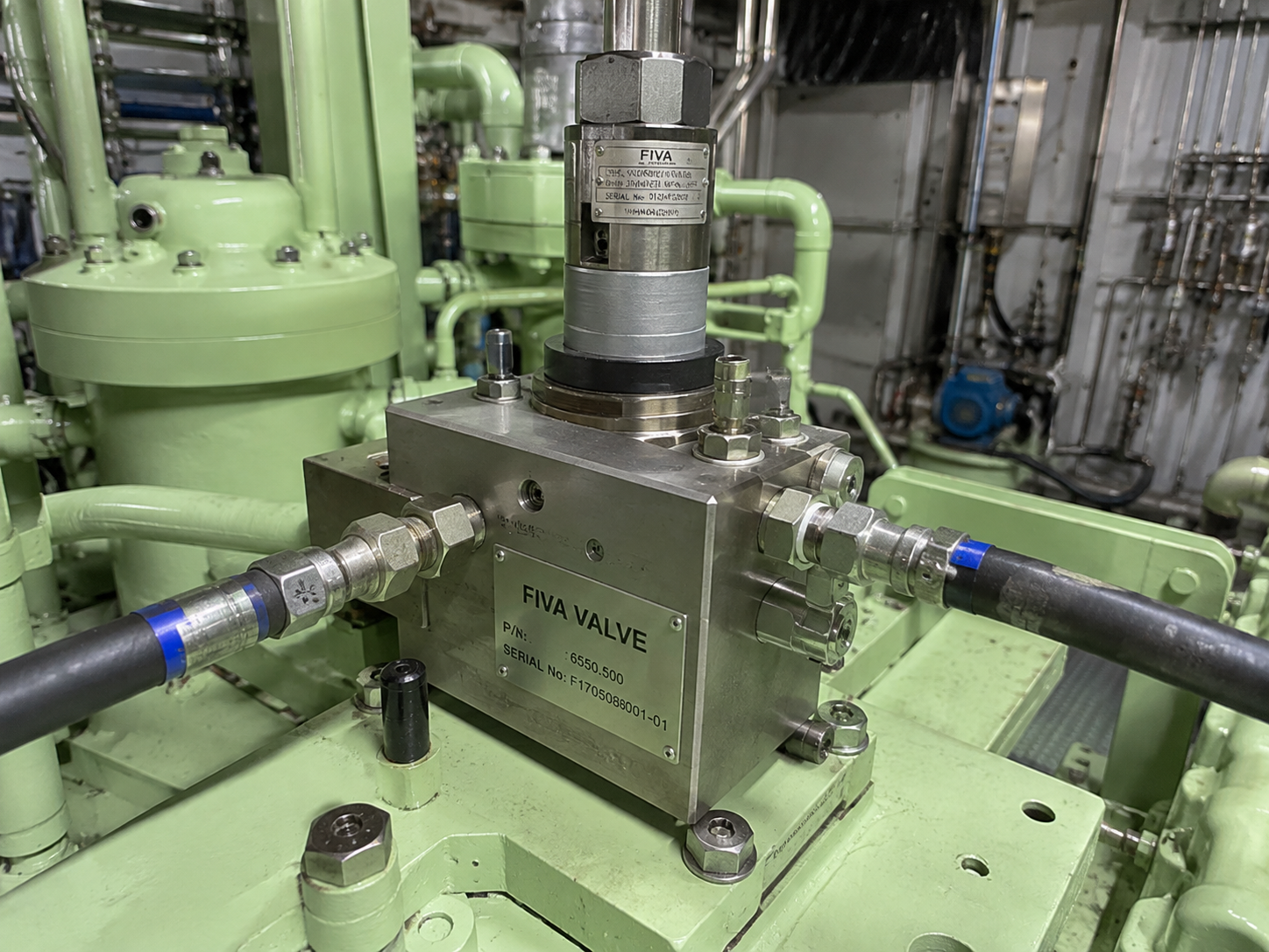
FIVA stands for Fuel Injection and Valve Actuation. On applicable MAN B&W ME-C engines, the FIVA valve is a cylinder-specific electro-hydraulic control valve assembly that directs pressurised servo oil according to electronic commands so the cylinder's fuel-injection and exhaust-valve actuation systems operate at the required timing. FIVA is not universal across every ME-C generation or configuration; some engines use separate ELFI and ELVA arrangements or other control architecture, so the exact engine model, Mark version and control-system revision must be confirmed before component-specific troubleshooting.
What is a FIVA valve?
A FIVA valve is the control interface between the ME-C electronic cylinder-control system and the hydraulic actuators used for fuel injection and exhaust-valve actuation on applicable engines. It receives an electrical command and directs hydraulic energy from the HPS to the relevant cylinder equipment.
The FIVA does not combust fuel, create fuel spray quality by itself, repair a pressure booster, form the exhaust-valve seat or close the exhaust valve mechanically. It controls servo-oil routing so downstream components can perform physical work. For this reason, FIVA valve troubleshooting must separate electronic command, hydraulic response and mechanical outcome.
Because arrangements vary, engineers should not assume every ME-C engine uses FIVA. Some electronically controlled MAN B&W configurations use separate ELFI for fuel injection and ELVA for exhaust-valve actuation, or different cylinder-control architecture. Spare-part identification and maker test procedures must match the actual engine.
Where the FIVA sits in the ME-C system
A simplified chain is: engine operating demand plus crank-angle information -> Engine Control System or CCU -> electrical command to FIVA -> FIVA controls HPS servo-oil flow -> fuel pressure booster or injection equipment and exhaust-valve actuator -> physical cylinder action -> performance and feedback information.
The electronic command is information. HPS pressure is hydraulic energy. Fuel-injection equipment and exhaust-valve actuators produce mechanical movement and cylinder effects. A fault at any point in this chain can appear as a FIVA valve fault, a combustion problem, a hydraulic problem or an ME-C cylinder control alarm.
FIVA, HPS and HCU clarification
The HPS, or Hydraulic Power Supply, provides the common pressurised servo oil. The FIVA meters or redirects that hydraulic energy for cylinder-specific fuel-injection and exhaust-valve functions where fitted. The HCU, where that terminology applies, contains or interfaces with cylinder-specific hydraulic actuation equipment depending on engine design.
These terms are often confused. Low or unstable HPS pressure can cause FIVA feedback alarms even if the FIVA valve itself is not damaged. A downstream HCU, actuator, pressure booster, exhaust-valve spindle or air-spring problem can also make a correct FIVA command look unsuccessful.
FIVA versus ELFI and ELVA
FIVA is a combined Fuel Injection and Valve Actuation arrangement used on certain engines. ELFI and ELVA refer to separate Electronic Fuel Injection and Electronic Exhaust Valve Actuation arrangements used on other configurations.
A symptom casually described as a FIVA fault on one vessel may involve ELFI, ELVA or another component on another vessel. Always confirm the installed control-system revision, drawing, spare-part number and maker documentation before diagnosis or ordering parts.
FIVA operating principle
Conceptually, an electronic command from the cylinder-control system moves the FIVA internal electro-hydraulic control element, spool or equivalent mechanism. That movement opens, closes or redirects servo-oil flow to the required actuator circuit.
Accurate response depends on the correct command, stable HPS pressure, adequate servo-oil flow, clean oil, sound internal clearances and sealing, free movement of precision control surfaces, healthy wiring/connectors and downstream actuator freedom.
This guide does not provide spool positions, port names, response times, electrical current values, stroke values, calibration settings or leakage limits. Those are engine and component specific.
FIVA role during fuel injection
The conceptual sequence is: injection timing calculation -> cylinder-control command -> FIVA hydraulic routing -> pressure booster or fuel-pump actuation -> high-pressure fuel generation -> fuel-valve opening -> injection -> end of hydraulic command and injection.
A correct FIVA response does not prove correct combustion. Fuel valve condition, pressure-booster condition, fuel quality, fuel temperature/viscosity, high-pressure pipe condition, compression and scavenge-air condition can still cause poor combustion, smoke or exhaust-temperature deviation.
FIVA role during exhaust-valve actuation
The conceptual sequence is: exhaust timing calculation -> FIVA command -> servo-oil routing -> exhaust-valve actuator movement -> valve opening -> hydraulic control change -> valve closing by air spring or closing arrangement where applicable.
Spindle sticking, seat leakage, guide wear, actuator leakage, air-spring faults, deposits or poor valve seating can produce symptoms that resemble a FIVA valve problem. Mechanical exhaust-valve condition must therefore be checked when symptoms point in that direction.
Command, position and feedback
Engineers should distinguish the electrical command sent to the FIVA, any available position or feedback signal, the hydraulic flow created by the valve and the actual mechanical outcome at fuel or exhaust-valve equipment.
A valid command does not prove the FIVA moved correctly. A feedback alarm does not automatically prove the valve body has failed. Wiring, connectors, feedback sensors, low servo pressure, contamination, internal leakage and downstream resistance can all create command/feedback disagreement.
FIVA feedback alarm
Possible causes include signal disagreement, internal wear, sticking, slow response, electrical connector problems, wiring faults, feedback or position-sensor issues where fitted, low or unstable servo pressure, oil contamination or downstream actuator resistance.
Before condemning the FIVA, check the first relevant alarm, whether the fault is continuous or intermittent, command versus feedback, connectors and wiring, control power/status, HPS pressure, oil cleanliness, leakage indicators and downstream actuator freedom.
Servo-oil supply and cleanliness
FIVA performance depends on stable hydraulic pressure and adequate flow from the HPS. Low HPS pressure, pressure fluctuation, filter restriction, oil contamination, accumulator problems where applicable or common hydraulic leakage can cause multiple cylinder-control symptoms.
FIVA assemblies contain precision hydraulic control surfaces and clearances. Contamination from maintenance ingress, dirty oil, filter issues, wear debris or water contamination can cause sticking, abrasive wear, internal leakage, slow response and recurring failures.
If one cylinder alone has abnormal timing, power or feedback while common pressure remains stable, local FIVA/control/actuation causes deserve attention. If several cylinders show similar faults, investigate common HPS, oil condition, control power or reference-signal problems first. This is reasoning, not a fixed rule.
Internal leakage versus external leakage
External leakage may be visible around the FIVA body, seals, fittings, pipework or related hydraulic blocks. Internal leakage may show as slow actuation, reduced effective hydraulic pressure, abnormal drain or return flow, excess heat or poor command response without obvious external oil loss.
Servo oil is a high-pressure hydraulic system. Inspection, isolation and depressurisation must follow maker and vessel procedures. Do not loosen pressurised connections or bypass safety interlocks to investigate leakage.
Common FIVA failure modes
Common failure modes include internal spool or control-element sticking, contamination, internal wear or erosion, excessive internal leakage, external seal leakage, slow response, incomplete movement, electrical actuator or solenoid problems where applicable, feedback/position-sensor faults where fitted, connector and wiring problems, hydraulic supply problems, incorrect installation, damaged seals, blocked or restricted passages and damage following contaminated hydraulic oil.
Each symptom should lead to checks, not instant replacement. Slow response may be contamination, low pressure, internal leakage or downstream mechanical resistance. A feedback alarm may be wiring, sensor, hydraulic or mechanical. Repeated failures after replacement often indicate an unresolved system cause.
FIVA component and diagnostic focus
| Component/Function | Possible Problem | Diagnostic Focus |
|---|---|---|
| Electronic actuator/control element | No response, slow response or intermittent operation | Command status, control-unit diagnostics, connectors and maker-approved checks |
| Internal hydraulic control element/spool | Sticking, wear, erosion or incomplete movement | Oil cleanliness, response evidence, bench-test results and contamination history |
| Servo-oil inlet/supply | Low pressure, restriction or unstable flow | HPS pressure trend, filters, oil condition and common cylinder symptoms |
| Outlet/control passages | Blocked, restricted or leaking paths | Hydraulic response, downstream actuator behaviour and workshop inspection |
| Feedback device where fitted | Signal disagreement or implausible position | Feedback trend, wiring, connectors, sensor status and authorised diagnostics |
| Seals | External leakage or internal bypass | Leakage location, drain/return behaviour and bench leakage test |
| Electrical connector | Loose pins, moisture, corrosion or cable damage | Plug/socket condition, cable route, shielding/grounding where applicable |
| Valve body | Damage, distortion or installation issue | Visual inspection, mounting condition and maker workshop assessment |
| Drain/return paths where applicable | Excessive flow, restriction or heat | Drain trend, temperature, internal leakage suspicion and test data |
Symptom, possible cause and inspection
| Symptom | Possible cause | Inspection |
|---|---|---|
| High exhaust temperature on one cylinder | Injection timing/quantity issue, exhaust-valve leakage, compression issue, fuel valve problem or FIVA/control issue | Compare alarms, command/feedback, fuel equipment, exhaust valve, compression and load |
| Low exhaust temperature on one cylinder | Low fuel delivery, misfire, delayed combustion, control command issue or fuel equipment defect | Review cylinder power, injection equipment, FIVA status and compression evidence |
| Cylinder power deviation | FIVA response issue, fuel-injection fault, exhaust-valve fault, compression loss or mechanical issue | Trend performance and inspect command/feedback, HPS, fuel system and exhaust valve |
| Rough or unstable operation | Cylinder control instability, poor combustion, hydraulic pressure fluctuation or mechanical fault | Check alarm chronology, HPS pressure, fuel valves, exhaust valves and cylinder balance |
| Injection timing-related alarm | FIVA control issue, crank-angle/reference issue, fuel actuator problem or feedback fault | Compare timing reference, FIVA feedback, HPS pressure and fuel equipment |
| Exhaust-valve timing/actuation alarm | FIVA routing issue, actuator leakage, air-spring issue, spindle sticking or feedback fault | Inspect FIVA status, actuator, air spring, spindle/seat and hydraulic supply |
| Repeated FIVA feedback alarm | Sticking, slow response, wiring fault, sensor issue, contamination or low servo pressure | Check first alarm, command/feedback, connectors, HPS and oil cleanliness |
| Intermittent FIVA alarm | Loose connector, vibration, moisture, intermittent pressure fluctuation or marginal feedback | Inspect wiring, plugs, event timing, pressure trend and environment |
| Slow FIVA response | Contamination, wear, varnish/deposits, low pressure, internal leakage or downstream loading | Check oil cleanliness, HPS, drain behaviour, actuator freedom and bench-test need |
| FIVA command/feedback mismatch | Feedback device fault, wiring issue, sticking valve, hydraulic restriction or internal wear | Compare command/status data and inspect electrical/hydraulic paths |
| External servo-oil leakage | Seal, fitting, pipe connection or valve-body interface leakage | Follow hydraulic safety procedures and inspect leakage source |
| Excessive drain/return flow where applicable | Internal leakage, worn sealing surfaces or damaged component | Compare with maker test guidance and inspect for heat/response issues |
| Abnormal valve-block temperature | Internal leakage, restriction, excessive cycling or nearby heat source | Check leakage, drain flow, command activity and hydraulic condition |
| One cylinder failing to fire | No/low injection, FIVA command issue, fuel equipment fault or compression problem | Check injection command path, fuel valves, pressure booster and compression |
| Poor combustion or smoke | Fuel injection issue, FIVA control issue, fuel quality, low compression or air shortage | Inspect fuel equipment, cylinder data, FIVA status and scavenge condition |
| Exhaust-valve closing issue | Air spring, spindle, seat, actuator release or FIVA/control issue | Inspect air spring, actuator, spindle/guide/seat and FIVA status |
| Multiple cylinders showing similar control faults | Common HPS, oil contamination, control power, timing reference or shared system issue | Check common alarms, HPS pressure, filters, oil condition and control supply |
| Recurring FIVA failures after replacement | Contamination, installation issue, downstream resistance, pressure instability or electrical supply problem | Investigate root cause before further replacement |
High or low exhaust-temperature diagnosis
Cylinder exhaust-temperature deviation can result from injection timing or quantity problems, fuel-valve defects, exhaust-valve timing or leakage, low compression, cylinder imbalance, air/scavenge issues or FIVA/control problems. FIVA should not be blamed solely from the temperature indication.
Useful evidence includes trend direction, load condition, alarm chronology, command/feedback status, cylinder pressure or indicator information where available, fuel-valve test results, exhaust-valve condition, scavenge observations and comparison with sister cylinders.
Cylinder power deviation workflow
- Review cylinder performance trend and operating condition
- Review alarm and event chronology, especially the first relevant alarm
- Compare command and feedback/status data where available
- Verify common HPS pressure and servo-oil condition
- Inspect FIVA electrical connectors and wiring
- Assess FIVA hydraulic response and leakage evidence
- Inspect related fuel-injection equipment and fuel-valve condition
- Inspect exhaust-valve actuator, spindle, guide, seat and air spring where applicable
- Verify compression and running-gear condition using maker-approved methods
Repeated FIVA feedback alarm workflow
- Check the first relevant alarm and event sequence
- Confirm whether the alarm is continuous, intermittent, load-related or vibration-related
- Compare command versus feedback or status data where available
- Inspect wiring, plugs, sockets, pins, moisture, corrosion and cable damage
- Verify control power and control-unit diagnostics
- Verify HPS pressure, pressure stability and servo-oil cleanliness
- Check external leakage and internal leakage indicators such as abnormal drain/return flow
- Assess downstream actuator freedom and mechanical resistance
- Consult maker diagnostic procedure before bench testing or replacement
How is a FIVA valve inspected onboard?
- Review alarm and event logs before removal
- Compare cylinder performance, exhaust temperature, power balance and operating trend
- Compare command and feedback/status data where available
- Review HPS pressure trend and common hydraulic alarms
- Review servo-oil cleanliness, filter history and contamination evidence
- Inspect electrical connectors, feedback wiring and local control data
- Inspect for external leakage, abnormal heat, vibration marks and damaged pipework
- Review drain/return behaviour where applicable
- Inspect related fuel-injection equipment and exhaust-valve condition
- Avoid removing the FIVA before basic system-level diagnosis is complete
Pre-removal and safe handling principles
Before removing a FIVA, confirm correct cylinder identification, symptom, alarm history, available diagnostic readings, common HPS condition, wiring/connector condition, downstream actuator condition and contamination history.
Removal and handling must follow maker procedures for hydraulic isolation, depressurisation, electrical isolation and vessel safety. High-level principles include extreme cleanliness, port protection, contamination prevention, component identification and protection of precision surfaces.
Workshop inspection and bench testing
Removed FIVA valves may require maker-approved specialist testing to assess electrical actuation, feedback or position response where applicable, hydraulic switching/control response, internal leakage, external leakage, controlled movement, repeatability and return-to-commanded state.
Bench testing helps separate valve condition from onboard wiring, HPS pressure, downstream actuator resistance and cylinder mechanical condition. Actual pressures, currents, stroke values, leakage limits, tolerances and pass/fail criteria must come from maker-approved documentation and test equipment.
What a FIVA bench test should establish conceptually
| Test Area | Purpose | Actual Limits |
|---|---|---|
| Electrical command response | Confirm response to approved command inputs | Maker-approved test procedure |
| Feedback plausibility | Confirm feedback agrees with commanded state where fitted | Engine/control-system specific |
| Hydraulic switching/control response | Confirm servo-oil routing changes correctly | Maker test equipment and documentation |
| Internal leakage | Identify bypass across worn or damaged internal surfaces | Approved leakage criteria only |
| External leakage | Confirm seals and body interfaces are tight under test | Approved pressure/test criteria only |
| Repeatability | Confirm stable response over repeated operation | Approved response criteria only |
| Return-to-commanded state | Confirm valve returns correctly after command change | Approved functional criteria only |
Dismantling, reconditioning and replacement decisions
FIVA dismantling and reconditioning should only be carried out where permitted by maker and workshop procedures. Precision internal parts, control surfaces, seals, actuator components and feedback equipment may require specialist inspection or renewal.
Not every FIVA is field-repairable. Unauthorised polishing, grinding, lapping, hydraulic-port modification or protected calibration adjustment should not be performed. Reuse, repair or replacement decisions should be based on maker bench-test results, wear, leakage, electrical/feedback condition, contamination history and approved overhaul criteria.
Root-cause investigation after repeated FIVA failures
Repeated FIVA faults should prompt investigation of servo-oil contamination, filter performance, water ingress, HPS pressure stability, downstream actuator resistance, installation or connection issues, abnormal heat, electrical supply quality and cylinder mechanical condition.
Replacing the FIVA without resolving the underlying cause can lead to repeat failure. A useful failure report should connect alarm sequence, oil condition, pressure history, component test results and cylinder mechanical findings.
Before replacing a FIVA
- Review alarm sequence and identify the first relevant alarm
- Compare cylinder trend data and sister-cylinder behaviour
- Compare command and feedback/status data where available
- Inspect electrical connectors, wiring and control-unit status
- Verify HPS pressure stability and common hydraulic alarms
- Review servo-oil cleanliness, filters and contamination history
- Check external leakage and internal leakage indicators
- Inspect pressure-booster and fuel-injection equipment
- Inspect exhaust-valve actuator, air spring, spindle, guide and seat condition
- Use maker diagnostic guidance before replacement
FIVA faults versus fuel-injection and exhaust-valve faults
A FIVA fault can mimic a fuel-injection fault because it controls hydraulic energy for injection actuation. Low power, poor combustion, smoke, abnormal exhaust temperature or timing alarms may involve FIVA, but they may also involve fuel valves, pressure boosters, fuel quality, compression or scavenge air.
A FIVA fault can also mimic an exhaust-valve fault. Timing alarms, high exhaust temperature or poor scavenging may involve FIVA routing, but spindle sticking, guide wear, seat leakage, air-spring problems or actuator leakage can create similar symptoms.
FIVA fault versus injector fault versus exhaust-valve fault
| Observed Symptom | FIVA/Control Possibility | Fuel-Injection Possibility | Exhaust-Valve/Mechanical Possibility | Useful Checks |
|---|---|---|---|---|
| Cylinder power loss | Poor hydraulic command execution | Fuel valve, booster or fuel quality issue | Compression loss or exhaust leakage | Command/feedback, fuel test, indicator/compression data |
| High exhaust temperature | Injection/exhaust actuation timing deviation | Poor atomisation or over-fuelling | Valve leakage or late/incomplete opening | Alarm trend, fuel valve, exhaust valve and scavenge checks |
| Smoke | Control timing/quantity issue | Injector leakage or poor spray | Poor scavenging or compression issue | Fuel equipment, air path and cylinder data |
| Timing alarm | FIVA response or feedback issue | Injection actuator downstream issue | Exhaust actuator or valve resistance | Command/status, HPS, actuator freedom |
| Poor combustion | Incorrect hydraulic routing or slow response | Fuel quality or fuel-valve defect | Low compression or blow-by | Fuel, compression, scavenge and FIVA evidence |
| Unstable operation | Intermittent control or hydraulic issue | Intermittent fuel delivery | Valve sticking or ring/liner issue | Event log, connectors, pressure trend and mechanical inspection |
Key condition indicators
| Observation/Data | Why It Matters | What Abnormal Behaviour May Suggest | Related Checks |
|---|---|---|---|
| FIVA alarm history | Shows sequence and recurrence | Feedback, command, hydraulic or electrical issue | First alarm, operating condition and event timing |
| Command/feedback agreement | Compares requested and reported response | Sticking, sensor, wiring or hydraulic problem | Connectors, HPS pressure and bench-test need |
| HPS pressure stability | Confirms common energy source | Common hydraulic supply fault | Filters, oil condition, leakage and multiple-cylinder symptoms |
| Servo-oil cleanliness | Protects precision clearances | Sticking, wear, leakage or repeated failures | Filters, samples, water/debris and maintenance ingress |
| External leakage | Shows visible hydraulic loss | Seal, fitting, pipe or body interface problem | Leak source under safe conditions |
| Drain/return behaviour | Can reveal internal leakage | Worn internal surfaces or bypass | Temperature, response and bench testing |
| Valve temperature | Can indicate leakage or restriction | Internal leakage, excessive cycling or nearby heat | Drain behaviour and hydraulic response |
| Cylinder exhaust temperature | Performance symptom | Fuel, exhaust, compression or FIVA issue | Cylinder trend and mechanical inspection |
| Cylinder pressure/performance data | Connects control to cylinder output | Combustion, compression or timing issue | Fuel, exhaust valve and running gear |
| Fuel-valve condition | Can mimic FIVA symptoms | Poor atomisation or leakage | Bench test and combustion evidence |
| Exhaust-valve behaviour | Can mimic FIVA symptoms | Sticking, leakage or air-spring issue | Actuator, spindle, seat and air spring |
Measurements and acceptance limits
FIVA condition assessment may involve maker-specified electrical checks, feedback or position verification, hydraulic response, internal and external leakage, HPS supply pressure, oil cleanliness, response repeatability and cylinder-performance data.
Actual numerical values, electrical readings, hydraulic pressures, leakage limits, response times, oil-cleanliness limits, temperatures, torques and acceptance criteria must come from the exact MAN B&W/Everllence engine instruction book, ME control-system documentation, FIVA workshop documentation, maker service bulletins, vessel procedures and class requirements.
Post-installation and functional verification
Post-installation work should confirm correct component identification, extreme cleanliness, correct seals and connections according to maker requirements, restoration of hydraulic and electrical connections, leakage inspection, alarm and feedback status, and response of the affected cylinder.
During controlled operation, engineers should compare exhaust temperature, cylinder performance and alarm status with sister units. This article does not provide universal tightening torques, hydraulic commissioning pressures or bypass procedures.
FIVA maintenance and prevention
Preventive attention should focus on servo-oil cleanliness, correct filtration, contamination control during maintenance, connector protection, leak inspection, alarm/event trend review, avoiding unnecessary dismantling and investigating recurring system causes.
Because FIVA influences fuel injection and exhaust-valve operation on applicable cylinders, faults can affect combustion, cylinder balance and exhaust-valve operation. Reliable diagnosis separates control, hydraulic and mechanical causes before component replacement.
FAQ
What does FIVA stand for?
FIVA stands for Fuel Injection and Valve Actuation.
What does a FIVA valve do on a MAN B&W ME-C engine?
On applicable engines, it directs pressurised servo oil according to electronic commands for cylinder fuel-injection and exhaust-valve actuation functions.
Does every ME-C engine use a FIVA valve?
No. Some configurations use FIVA, while others may use separate ELFI and ELVA components or different control architecture.
What is the difference between FIVA and ELFI/ELVA?
FIVA combines fuel injection and valve actuation functions on applicable arrangements. ELFI and ELVA refer to separate electronic fuel-injection and exhaust-valve actuation arrangements where fitted.
What is the difference between FIVA and HPS?
The HPS supplies pressurised servo oil. The FIVA directs or meters that hydraulic energy for cylinder-specific functions.
What is the difference between FIVA and HCU?
The HCU is cylinder-level hydraulic equipment or interface depending on design; FIVA is the electro-hydraulic control valve used in certain arrangements.
How does FIVA control fuel injection?
It routes servo oil according to the injection command so downstream pressure-booster or injection equipment can generate high-pressure fuel delivery.
How does FIVA control the exhaust valve?
It routes servo oil according to the exhaust-valve command so the exhaust-valve actuator can open the spindle; closing depends on the installed closing arrangement.
What causes a FIVA feedback alarm?
Possible causes include sticking, slow response, sensor or feedback issue, wiring fault, connector problem, low servo pressure, contamination or downstream resistance.
What causes a FIVA valve to stick?
Contamination, deposits or varnish where relevant, wear, damaged control surfaces, low pressure or downstream actuator loading can contribute.
Can dirty servo oil damage a FIVA?
Yes. Contamination can cause sticking, abrasive wear, internal leakage and repeated failures.
Can low HPS pressure cause a FIVA alarm?
Yes. If the common hydraulic energy source is unstable or low, FIVA response and feedback can be affected.
What causes servo-oil leakage around a FIVA?
Possible sources include seals, fittings, pipe connections, valve-body interfaces or adjacent hydraulic blocks.
Can a FIVA fault cause high exhaust temperature?
It can, but high exhaust temperature can also come from fuel injection, exhaust-valve leakage, compression or air/scavenge issues.
How do engineers know whether the FIVA or injector is faulty?
They compare command/feedback, HPS condition, fuel-valve test evidence, cylinder pressure/performance and combustion symptoms.
How do engineers distinguish a FIVA problem from an exhaust-valve problem?
They compare FIVA status with actuator response, air spring condition, spindle freedom, seat leakage and exhaust-valve inspection evidence.
Can a FIVA valve be overhauled?
Only where maker-approved workshop procedures permit it. Some faults require specialist repair or replacement.
How is a FIVA bench tested?
With maker-approved equipment to check command response, feedback, hydraulic control, leakage and repeatability using configuration-specific limits.
What should be checked before replacing a FIVA?
Alarm sequence, command/feedback, wiring, connectors, HPS pressure, oil cleanliness, leakage, fuel equipment, exhaust-valve equipment and maker diagnostics.
Why do FIVA faults sometimes return after replacement?
The root cause may remain: contaminated servo oil, unstable HPS pressure, downstream resistance, wiring faults or installation issues.
Technical glossary
| Term | Meaning |
|---|---|
| FIVA | Fuel Injection and Valve Actuation; electro-hydraulic control valve arrangement used on applicable engines. |
| HPS | Hydraulic Power Supply; common source of pressurised servo or hydraulic oil. |
| HCU | Hydraulic Cylinder Unit or cylinder-level hydraulic equipment/interface where applicable. |
| CCU | Cylinder Control Unit or cylinder-specific control hardware where that terminology applies. |
| Servo oil | Hydraulic working oil used for ME-C control and actuation functions where applicable. |
| Electro-hydraulic control | Electrical command controlling hydraulic oil flow to create mechanical action. |
| Command signal | Electronic instruction sent by the control system. |
| Feedback signal | Returned status or position information where fitted. |
| Internal leakage | Hydraulic bypass inside a component without visible external oil loss. |
| Fuel pressure booster | Downstream equipment that helps generate high-pressure fuel injection where applicable. |
| Exhaust-valve actuator | Hydraulic actuator that moves the exhaust-valve spindle where applicable. |
Measurements and acceptance limits
Condition assessment should be based on recorded measurements, visual findings, operating symptoms, and the applicable maker documentation. Acceptable limits should be confirmed against the applicable manufacturer's manual and engine-specific technical documentation.
Need technical assistance?
If inspection, overhaul, troubleshooting, workshop repair, or onboard attendance is required, Dieselmech Group can review the symptoms, engine details, operating history, and available measurements before recommending the next practical step. Contact us at +65 6334 1855, email sales@dieselmech.com.sg, or submit an enquiry through the Contact Us page.
Technical note
This article is for general technical information. Actual procedures, limits, clearances, pressures, temperatures, torque values, and renewal criteria depend on the engine model, configuration, maker revision, service bulletin, vessel procedures, and class requirements. Manufacturer manuals and vessel safety procedures take precedence. Safety-critical work should be carried out by appropriately qualified personnel.
Published by Dieselmech Group Technical Team. For advice on a specific engine or fault, contact our marine engineers.