-DQG-c1Ek.png)
Technical Article
Connecting Rod Inspection and Bearing Checks
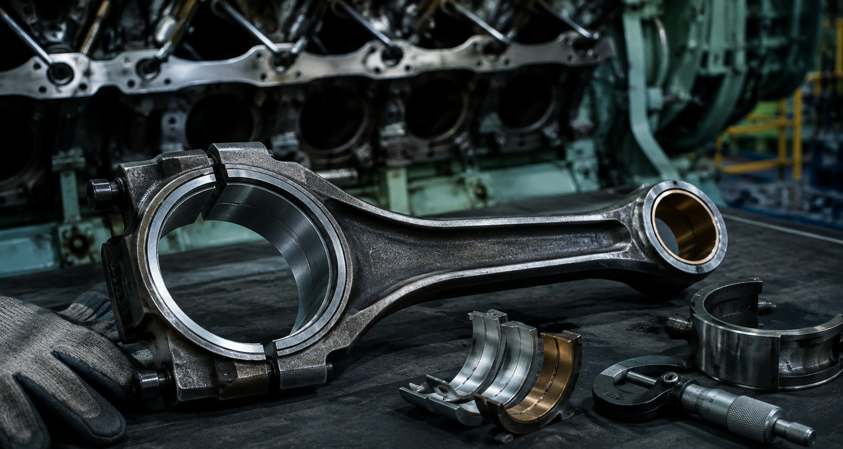
Connecting rod inspection verifies the rod body, big-end bearing housing, small-end bush where applicable, bearing shells, crankpin, fasteners, lubrication path, mating faces, alignment, and recorded measurements. Bearing checks focus on clearance, crush and seating evidence, overlay condition, wiping, scoring, fatigue, embedded particles, overheating, fretting, oil supply, and the root cause of any abnormal wear.
Function of the connecting rod and bearings
A marine engine connecting rod transmits combustion and inertia loads between the piston assembly and the crankshaft. In four-stroke trunk-piston engines and many auxiliary engines, the rod usually connects the gudgeon or wrist pin at the small end to the crankpin at the big end. In low-speed two-stroke crosshead engines, the load path is different because the connecting rod works between the crosshead and the crankpin rather than using the same trunk-piston small-end arrangement.
The connecting rod is subject to alternating compressive and tensile loading. Combustion pressure pushes the piston or crosshead down through the rod, while inertia loads during direction changes can load the rod and fasteners in tension. Because failure can cause severe crankcase, crankshaft, cylinder block, and personnel-safety consequences, connecting-rod integrity is treated as safety-critical work.
The big-end bearing supports the rod on the crankpin and must maintain a stable lubricating-oil film under high cyclic load. Where fitted, the small-end bush supports the gudgeon pin and depends on correct geometry, clearance, oil supply, and bush security. A bearing shell, bush, crankpin, oil drilling, or fastener defect should not be treated as an isolated part failure until the surrounding components and operating history have been checked.
When should connecting rods and bearings be inspected?
Inspection intervals and required scope are engine-specific. A connecting rod that appears acceptable visually can still require dimensional checks, NDT, fastener renewal, or maker review depending on the engine type, running hours, operating event, and service history.
- At maker-specified overhaul intervals or during scheduled piston, cylinder-unit, or auxiliary-engine overhaul
- After bearing-temperature alarms, abnormal temperature trends, low lubricating-oil pressure, or abnormal oil temperature
- When metallic debris, bearing material, or abnormal particle findings are found in filters, strainers, magnetic plugs, drain oil, or oil analysis
- After knocking noise, crankcase abnormality, vibration, overload, overspeed, seizure, wiping, or suspected lubrication failure
- When crankpin damage, abnormal clearance, bearing-shell movement, fretting at the big-end joint, or previous rod-fastener problems are suspected
- Following any event where the engine maker, vessel SMS, class, or superintendent requires additional inspection before continued operation
Pre-inspection assessment
Before dismantling, engineers should collect enough context to interpret the inspection correctly. Useful information includes engine model, cylinder or unit identification, running hours, previous bearing renewal, previous big-end and small-end measurements, previous crankpin measurements, lubricating-oil analysis, filter findings, bearing-temperature trends, oil pressure and temperature history, alarm history, abnormal noise or vibration, and recent operating events.
Fastener history is especially important. Records should show whether connecting-rod bolts, studs, nuts, or hydraulic tightening components were renewed, measured, reused, or tightened by a maker-approved method. Previous crankpin grinding, polishing, bearing damage, or alignment findings should also be reviewed before judging the new inspection result.
Dismantling and component identification
Connecting-rod work requires strict component identification. The cylinder number, rod identity, cap position, bearing-shell position, fasteners, shims or locating components where fitted, and mating parts should be controlled so that matched components are not mixed. Bearing shells should be inspected and photographed before cleaning removes useful contact evidence.
Machined surfaces, crankpins, bearing backs, serrations, and mating faces must be protected from impact and contamination. Actual lifting, dismantling, fastener release, turning gear, crankcase-entry, lockout, and safety procedures must follow the applicable maker manual and vessel safety-management system.
Connecting-rod body inspection
The rod body should be inspected for cracks, deformation, bending, twist, corrosion, erosion, impact marks, surface defects, abnormal contact marks, overheating, and discoloration. Stress-concentration areas such as section transitions, fillets, machined corners, bolt areas, cap registers, serrations, and oil-drilling exits require particular attention.
Visual inspection is only one part of the assessment. Where required by the maker, class, repair procedure, or observed damage, non-destructive testing may be needed. Magnetic-particle inspection, dye-penetrant inspection, ultrasonic inspection, or other methods may be appropriate depending on material and design, but no single NDT method should be assumed suitable for every connecting rod.
Big-end inspection
The big end should be checked as a housing system, not only as a place where the bearing shell sits. Inspect the big-end bore, cap, split line, mating faces, serrations where fitted, bearing seating surfaces, locating features, bolt seating areas, and any signs of movement or deformation.
Fretting, polishing, indentation, corrosion, poor shell-back contact, crushed dirt, or uneven witness marks can indicate movement, loss of support, housing distortion, inadequate bearing crush, poor assembly, or fastener problems. Correct big-end geometry is essential for bearing shell support, oil-film formation, bearing clearance, and even load distribution around the crankpin.
Where specified, big-end bore diameter, roundness, ovality, cap seating, and related geometry should be measured with calibrated equipment at maker-defined positions. Numerical acceptance limits must come from the applicable engine documentation.
Small-end inspection on trunk-piston engines
On four-stroke trunk-piston engines, the small end normally works with a gudgeon or wrist pin and a bush or bearing arrangement. Inspection should cover bush bore condition, pin contact pattern, scoring, overheating, cracking, lubrication grooves, oil holes, bush security, pin surface condition, pin retention, and evidence of poor lubrication.
Where specified, measurements may include small-end bush internal diameter, gudgeon-pin diameter, pin-to-bush clearance, bush ovality, and related alignment checks. Low-speed crosshead engines use a different connecting-rod and crosshead arrangement and should not be described as having the same conventional trunk-piston small-end bush system.
Bearing-shell inspection
Bearing shells should be inspected on the running surface, overlay, lining, backing, parting areas, locating features, oil grooves, and shell back. Common findings include normal polishing, wiping, smearing, scoring, scratching, fatigue cracking, pitting, flaking, cavitation or erosion where relevant, embedded particles, contamination damage, edge loading, local overheating, corrosion, shell-back fretting, poor contact, and abnormal wear patterns.
Appearance gives evidence, but it is not a complete diagnosis by itself. Wiping may point toward loss of oil film, overheating, overload, insufficient clearance, contaminated oil, incorrect assembly, or restricted supply. Edge loading may point toward misalignment, crankpin taper, rod distortion, housing problems, or assembly error. Repeated bearing damage should always trigger crankpin, lubrication, housing, alignment, and fastener checks.
Bearing crush, seating and back contact
Bearing crush is the designed interference that helps the shell seat firmly in the housing when the cap is tightened. Correct seating supports heat transfer, keeps the shell stable, and helps maintain the designed oil clearance. Locating tabs or features position the shell, but they should not be treated as the main feature preventing all shell movement.
Shell-back fretting, bright polishing, black residue, local contact marks, damaged tabs, or uneven back contact can indicate movement, poor seating, housing distortion, dirt under the shell, loss of crush, or incorrect assembly. Universal crush values should not be used; the applicable maker procedure determines how seating and crush are assessed.
Crankpin inspection
A damaged bearing should never be assessed without inspecting the crankpin. The crankpin journal should be checked for scoring, polishing, ridging, wiping transfer, corrosion, cracks, heat discoloration, oil-hole condition, oil-hole edge damage, surface defects, and dimensional condition.
Where specified, crankpin checks include diameter, ovality, taper, surface condition, and comparison with previous records. A renewed bearing installed on a crankpin with taper, ovality, embedded transfer, sharp oil-hole edges, or surface damage can fail rapidly even if the new bearing shell is correct.
Connecting-rod bolts, studs, nuts and fasteners
Connecting-rod fasteners are critical loaded components. Inspect threads, shanks, seating faces, nuts, washers where fitted, corrosion, fretting, necking, impact damage, galling, deformation, and evidence of incorrect tightening. Previous tightening records, renewal history, and any maker limits on reuse should be reviewed.
Some engines require bolt stretch, elongation, or length measurement as part of acceptance. Some connecting-rod bolts are mandatory replacement items or have restricted reuse rules. A bolt must never be considered reusable simply because it looks visually acceptable. Reassembly must follow the specified tightening sequence and maker-approved torque, hydraulic, angle, or elongation method as applicable.
Serrated and mating-face inspection
Where serrated joints, registers, dowels, fitted bolts, or machined mating faces are used, cleanliness and correct engagement are essential. Inspect for fretting, indentation, dirt, raised burrs, corrosion, deformation, loss of contact, incorrect cap fit, and evidence that the cap or joint has moved in service.
Damaged mating geometry can change big-end alignment, reduce bearing support, disturb crush, and create uneven bearing loading. Any repair to mating geometry must be approved for the specific rod and engine design.
Oil passages and lubrication inspection
Oil drillings, grooves, crankpin oil holes, small-end lubrication paths, and bearing-shell oil features should be checked for sludge, obstruction, damaged edges, incorrect assembly, contamination, and evidence of poor oil supply. When wiping or overheating is found, the oil path should be traced rather than simply replacing the damaged bearing.
Lubricating-oil pressure, temperature, viscosity condition, contamination, filter bypass history, cooler performance, oil-pump condition, relief-valve behaviour, and recent oil maintenance can all affect connecting-rod bearing life.
Key measurements and checks
| Component/Area | Measurement or Check | Why It Is Checked | Possible Significance of Abnormal Findings |
|---|---|---|---|
| Connecting-rod body | Visual condition, cracks, deformation, corrosion, overheating and NDT where specified | Confirms structural integrity under alternating load | Cracking, distortion, corrosion or heat damage may require maker review, repair approval or renewal |
| Rod straightness/alignment | Bend, twist or alignment check where maker-specified | Confirms load path between piston/crosshead and crankpin | Misalignment can create edge loading, piston/liner issues and premature bearing wear |
| Big-end bore | Diameter and geometry at specified positions | Confirms housing support for bearing shells | Distortion can affect crush, clearance and oil-film stability |
| Big-end ovality/roundness | Roundness or ovality measurement where specified | Checks whether cap and rod housing remain geometrically correct | Ovality may indicate overload, joint movement, incorrect tightening or housing damage |
| Mating faces or serrations | Cleanliness, fretting, indentation, contact and engagement | Ensures cap location and bearing support | Damage can alter big-end alignment and shell seating |
| Small-end bush where applicable | Internal diameter, wear, scoring, cracks, oil grooves and security | Confirms gudgeon-pin support on trunk-piston engines | Wear or poor lubrication can cause pin knock, seizure or piston alignment problems |
| Gudgeon or wrist pin where applicable | Diameter, surface condition, cracks, heat marks and contact pattern | Confirms the pin will not damage the bush or piston bosses | Scoring, taper or overheating can indicate lubrication failure or abnormal load |
| Small-end clearance | Pin-to-bush clearance by maker-approved method | Checks oil film and mechanical support | Excess or insufficient clearance can cause knock, heat, seizure or poor alignment |
| Bearing-shell surface | Overlay, lining, scoring, wiping, fatigue, embedded debris and edge wear | Shows bearing condition and failure evidence | Patterns may indicate oil starvation, contamination, misalignment, overload or crankpin defects |
| Bearing clearance | Direct dimensional measurement or other maker-specified method | Confirms oil-film space between shell and crankpin | Incorrect clearance can cause low oil pressure, overheating, wiping, knock or fatigue |
| Bearing seating/back contact | Shell-back contact, fretting, polishing, tabs and housing marks | Confirms shell support and stability | Movement or poor contact can cause overheating, crush loss and repeat failure |
| Crankpin diameter | Journal diameter at specified positions | Confirms crankpin size and bearing compatibility | Undersize or uneven diameter can alter clearance and contact |
| Crankpin ovality | Out-of-round condition by specified measurement | Checks journal geometry under bearing load | Ovality can disturb oil film and create repeated bearing distress |
| Crankpin taper | Diameter difference along journal length | Checks parallel support across bearing width | Taper can create edge loading and uneven wear |
| Crankpin surface condition | Scoring, ridging, heat marks, cracks, oil-hole edges and corrosion | Prevents renewed bearing damage | Surface defects can rapidly wipe or score a new shell |
| Rod bolts/studs/nuts | Thread, seating condition, corrosion, damage, length or elongation where specified | Confirms clamping force and fastener integrity | Overstretch, damage or unknown reuse history may require renewal |
| Oil passages | Cleanliness, flow path, grooves, drillings and oil holes | Confirms oil supply to bearing and bush | Restriction can cause wiping, overheating or seizure |
| Axial or side clearance where applicable | Rod side clearance or axial freedom by maker procedure | Confirms correct mechanical freedom and oil escape path | Abnormal clearance may indicate wear, assembly error or thrust/contact issues |
Bearing-clearance measurement concepts
Big-end bearing clearance may be assessed by direct dimensional measurement of crankpin and bearing bore, by lead-wire or plastigage-type methods where the maker permits, or by other engine-specific procedures. The method must be suitable for the bearing design, engine size, and maker requirements.
No universal clearance value should be applied across marine engines. Clearance interpretation depends on crankpin size, bearing material, shell thickness, housing condition, oil viscosity, engine speed, loading, and the maker's acceptance criteria.
Measurement accuracy and recording
Measurements should be made with calibrated equipment on clean, damage-free surfaces at the positions stated by the maker. Component temperature, cleanliness, measuring pressure, repeatability, and instrument condition can affect results. Measurements should identify engine, cylinder, unit, rod number, shell position, crankpin, date, running hours, instrument, and technician.
Trend comparison is often more useful than a single reading. Previous crankpin, bearing clearance, bolt elongation, and oil-analysis records can show whether wear is stable, progressive, sudden, or linked to a specific event.
Connecting-rod alignment and geometry
Rod bend, twist, big-end distortion, small-end wear, incorrect cap assembly, or mating-face damage can create abnormal loading. Symptoms may include uneven bearing contact, edge loading, piston skirt wear, liner scuffing, abnormal vibration, and repeat bearing distress.
Alignment checks should follow maker requirements and approved workshop procedures. Tolerances and acceptance criteria are engine-specific and should not be inferred from another engine model.
Bearing failure modes and diagnosis
Bearing wiping or smearing usually indicates that the oil film has broken down, but the cause can be oil starvation, insufficient clearance, excessive temperature, overload, contamination, misalignment, incorrect assembly, crankpin defects, or a combination of factors. Scoring and embedded particles often point toward contamination, but the source may be dirty assembly, filter bypass, previous damage, poor flushing, or particles released from another component.
Fatigue cracking, overlay loss, pitting, flaking, cavitation or erosion, edge loading, corrosion, overheating, seizure, shell-back fretting, and abnormal polishing should be investigated with the oil system, crankpin, bearing housing, rod alignment, fasteners, load history, and maintenance history before deciding the root cause.
Symptom, possible cause and inspection
| Symptom | Possible cause | Inspection |
|---|---|---|
| Bearing wiping | Loss of oil film, restricted oil supply, overload, incorrect clearance, misalignment or contamination | Inspect bearing surface, oil path, oil pressure history, crankpin and housing geometry |
| Bearing overheating | Oil starvation, excessive load, incorrect clearance, poor seating or high oil temperature | Check bearing temperature trend, shell back, oil supply, crankpin and clearance |
| Knocking noise | Excessive bearing clearance, small-end wear, bearing damage or fastener issue | Check big-end clearance, small-end bush, crankpin and rod fasteners |
| Low lubricating-oil pressure | Excessive bearing clearance, oil-pump issue, leakage, relief-valve issue or low viscosity | Check bearing clearances, oil system, temperature, filters and pump condition |
| Abnormal bearing-temperature trend | Developing distress, oil-flow restriction, overload or clearance change | Compare trends and inspect bearing, oil path and crankpin |
| Metallic debris in oil/filter | Bearing overlay, lining, crankpin damage or other engine wear | Identify material, inspect filters, bearing shells, crankpin and related components |
| Fretting at big-end joint | Joint movement, poor mating-face contact, fastener issue or incorrect assembly | Inspect serrations/mating faces, bolt records, big-end geometry and shell back |
| Abnormal shell-back polishing | Shell movement, inadequate seating, housing distortion or loss of crush | Inspect housing, shell back, locating features, mating faces and fastener condition |
| Uneven bearing wear | Misalignment, crankpin taper, rod distortion, housing issue or assembly error | Measure crankpin, check rod alignment, big-end geometry and bearing contact pattern |
| Edge loading | Crankpin taper, rod misalignment, housing distortion or cap seating issue | Measure taper, inspect rod geometry, mating faces and bearing marks |
| Scoring | Hard particles, crankpin roughness, oil contamination or dirty assembly | Inspect oil cleanliness, filters, crankpin surface and bearing grooves |
| Embedded particles | Contaminated oil, debris from previous failure or inadequate cleaning | Inspect oil system, filters, flushing history and other damaged components |
| Fatigue cracking | Cyclic overload, incorrect clearance, poor support, crankpin defects or long service | Inspect load history, clearance, shell support, crankpin and housing |
| Crankpin scoring | Bearing failure, contamination, oil-hole edge damage or foreign particles | Inspect crankpin surface, oil holes, shell debris and lubrication path |
| Repeated bearing failures | Unresolved root cause such as crankpin geometry, oil supply, housing distortion or alignment | Review full history and recheck oil system, crankpin, rod, fasteners and assembly procedure |
| Excessive bearing clearance | Wear, wrong shell, crankpin undersize, housing issue or assembly error | Measure crankpin and bearing bore, confirm shell identity and inspect housing |
| Restricted oil supply | Blocked drilling, sludge, incorrect assembly, low oil pressure or damaged oil hole | Trace oil path and verify drillings, grooves, pump, filters and relief valves |
| Abnormal vibration | Bearing damage, rod misalignment, looseness, piston/liner issue or crankshaft issue | Inspect bearing, rod geometry, piston condition, crankshaft and vibration trend |
Root-cause investigation after bearing damage
A damaged connecting-rod bearing should not simply be renewed and returned to service without investigation. The root-cause review should include lubrication supply, oil pressure and temperature, oil cleanliness, filter findings, oil passages, bearing clearance, shell seating, big-end housing geometry, crankpin diameter, crankpin ovality, crankpin taper, crankpin surface condition, rod alignment, fastener condition, recent assembly work, load history, overspeed or overload events, and crankcase findings.
If the cause is not found, a new shell can fail quickly and may cause more severe damage than the original defect. Repeat failures should be escalated for maker, specialist workshop, class, or superintendent review as appropriate.
Reuse, reconditioning or renewal decisions
Connecting rods, bushes, bearing shells, crankpins, and fasteners must be assessed individually. Decisions should consider maker criteria, measured condition, NDT findings where applicable, material condition, operating event, previous repair history, and class or vessel requirements.
Bearing shells are generally assessed according to maker renewal criteria and failure evidence. Bush replacement, crankpin polishing or grinding, connecting-rod repair, machining, re-metalling, and other reconditioning work should only be performed where approved for the specific engine and component.
Reassembly requirements
Reassembly should begin with final cleanliness. Oil passages should be verified, crankpin condition and measurements confirmed, bearing-shell identity and orientation checked, and shell-back and housing conditions prepared exactly as required by the maker procedure. Dirt, burrs, oil where dry seating is required, damaged locating features, or incorrect shell orientation can create immediate bearing problems.
Rod and cap engagement, serration fit, fastener inspection or renewal, lubrication of specified running surfaces, tightening sequence, locking arrangements, bearing clearance, side clearance where applicable, and crankshaft rotation checks should all follow the maker procedure. Universal torque figures, hydraulic pressures, tightening angles, or elongation values must not be substituted.
Post-reassembly and post-overhaul checks
After reassembly, checks may include manual turning or jacking where applicable, verification that the crankshaft rotates freely, lubrication priming, leak checks, crankcase inspection, confirmation of oil pressure, initial start monitoring, controlled load-up, bearing-temperature monitoring, oil temperature and pressure trending, abnormal noise checks, vibration checks, and follow-up inspection where required.
Post-overhaul monitoring should be compared with pre-overhaul trends. A normal first start does not by itself prove that root cause has been eliminated if the original bearing distress was linked to oil contamination, crankpin geometry, alignment, or assembly history.
Bearing appearance, possible cause and additional checks
| Bearing Appearance | Possible Cause | Additional Checks |
|---|---|---|
| Wiping or smearing | Oil-film breakdown, overheating, overload, low oil supply or incorrect clearance | Check oil pressure, temperature, passages, clearance, crankpin and load history |
| Scoring or scratches | Hard particles, dirty assembly, crankpin roughness or contamination | Inspect filters, oil samples, crankpin surface, oil grooves and flushing history |
| Embedded debris | Contaminated lubricating oil or debris from previous failure | Identify particle material and inspect oil system, filters and other bearings |
| Fatigue cracks | Cyclic overload, poor shell support, incorrect clearance or long service | Check bearing seating, housing geometry, crankpin condition and operating load |
| Edge wear | Misalignment, crankpin taper, rod bend, housing distortion or cap fit issue | Measure crankpin taper and ovality, inspect rod alignment and mating faces |
| Overheating or discoloration | Oil starvation, excessive friction, poor seating or high oil temperature | Check oil supply, temperature trend, shell back and crankpin surface |
| Shell-back fretting | Shell movement, poor seating, insufficient support or joint movement | Inspect housing bore, bearing crush concept, mating faces and fasteners |
| Uneven polishing | Uneven load distribution, crankpin geometry issue or housing distortion | Check crankpin measurements, big-end bore, rod alignment and assembly records |
Four-stroke trunk-piston rods versus low-speed crosshead rods
Four-stroke trunk-piston engines usually place the connecting rod between the gudgeon pin and crankpin, so inspection focuses on the rod body, big-end bearing, small-end bush, gudgeon pin, rod bolts, lubrication, and piston alignment. This is common in auxiliary engines and medium-speed propulsion engines.
Low-speed two-stroke crosshead engines use a different arrangement. The connecting rod works between the crosshead and the crankpin, while piston side thrust is handled through the crosshead guide system rather than the trunk piston bearing directly against the liner in the same way. Inspection focus includes crankpin bearing condition, crosshead-related interfaces, lubrication, fasteners, alignment, and maker-specific bearing arrangements. Terminology and procedures should not be copied blindly between these engine types.
FAQ
What should be checked on a marine engine connecting rod?
Check the rod body, big-end housing, bearing shells, crankpin, fasteners, mating faces or serrations, oil passages, alignment, and small-end bush or crosshead interface as applicable to the engine design.
What causes connecting-rod bearing failure?
Common contributors include oil starvation, contamination, incorrect clearance, overload, crankpin defects, housing distortion, misalignment, poor seating, fastener problems, incorrect assembly, or unresolved damage from a previous event.
What does bearing wiping indicate?
Bearing wiping indicates loss or breakdown of the oil film at the bearing surface. It does not prove one cause by itself, so oil supply, clearance, crankpin condition, loading, alignment, and assembly history should be checked.
What causes fretting at the big-end joint?
Fretting can be caused by joint movement, poor mating-face contact, damaged serrations, inadequate clamping, fastener issues, dirt between faces, or incorrect assembly.
How is connecting-rod bearing clearance checked?
Clearance is checked by the maker-approved method for the engine, such as dimensional measurement or another specified technique. The acceptance value must come from the engine-specific documentation.
Why is crankpin ovality measured?
Crankpin ovality shows whether the journal is out of round. Excessive ovality can disturb oil-film formation, change bearing clearance during rotation, and cause repeated bearing distress.
What causes uneven bearing wear?
Uneven bearing wear may be caused by crankpin taper, rod misalignment, big-end housing distortion, poor cap seating, edge loading, assembly error, or abnormal loading.
Can connecting-rod bolts be reused?
Only if the maker permits reuse and all inspection, length, elongation, tightening-history, and condition requirements are satisfied. A bolt should never be reused simply because it looks visually acceptable.
What is bearing crush?
Bearing crush is the designed interference that helps the shell seat firmly in the housing when the cap is tightened. It supports heat transfer, shell stability, and correct bearing operation.
Why is shell-back contact important?
Good shell-back contact supports the bearing, transfers heat, and helps prevent shell movement. Fretting or uneven back contact can indicate poor seating, housing problems, or loss of support.
What should be checked after a bearing failure?
Check oil pressure and temperature, oil cleanliness, oil passages, filters, crankpin geometry and surface, bearing clearance, housing geometry, rod alignment, fasteners, assembly history, and operating events.
When should a connecting rod be renewed?
Renewal depends on maker criteria, measured condition, NDT findings, cracks, deformation, fastener or mating-face condition, repair history, and whether approved reconditioning is possible for that component.
What is checked on the small-end bush?
On trunk-piston engines, engineers check bush wear, scoring, cracking, overheating, lubrication grooves and holes, bush security, pin contact, and pin-to-bush clearance where specified.
How does a crosshead-engine connecting rod differ from a four-stroke connecting rod?
A four-stroke trunk-piston rod usually connects the gudgeon pin to the crankpin. A low-speed crosshead-engine rod connects the crosshead to the crankpin, with a different load path and different inspection focus.
Measurements and acceptance limits
Condition assessment should be based on recorded measurements, visual findings, operating symptoms, and the applicable maker documentation. Acceptable limits should be confirmed against the applicable manufacturer's manual and engine-specific technical documentation.
Need technical assistance?
If inspection, overhaul, troubleshooting, workshop repair, or onboard attendance is required, Dieselmech Group can review the symptoms, engine details, operating history, and available measurements before recommending the next practical step. Contact us at +65 6334 1855, email sales@dieselmech.com.sg, or submit an enquiry through the Contact Us page.
Technical note
This article is for general technical information. Actual procedures, limits, clearances, pressures, temperatures, torque values, and renewal criteria depend on the engine model, configuration, maker revision, service bulletin, vessel procedures, and class requirements. Manufacturer manuals and vessel safety procedures take precedence. Safety-critical work should be carried out by appropriately qualified personnel.
Published by Dieselmech Group Technical Team. For advice on a specific engine or fault, contact our marine engineers.