-DQG-c1Ek.png)
Technical Article
Marine Engine Crankshaft Inspection and Deflection Measurement
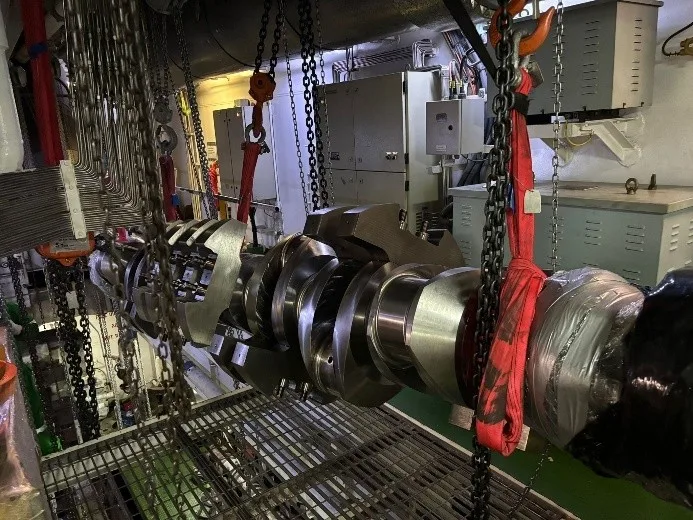
Marine engine crankshaft inspection checks main journals, crankpins, crank webs, fillets, oil holes, bearing contact evidence, cracks, scoring, heat marks, ovality, taper, runout where applicable, lubrication condition and crankshaft deflection. Deflection readings help indicate changes in supported alignment, but they must be interpreted with bearing condition, vessel loading, temperature, foundation condition and historical trends.
Function and loading of a marine engine crankshaft
The crankshaft converts reciprocating piston or crosshead motion into rotary motion for propulsion or power generation. Combustion force is transmitted through the piston, connecting rod or crosshead system into the crankpin, crank webs and main journals. Inertia loads from reciprocating and rotating components continuously change direction and magnitude.
On large low-speed two-stroke main engines, crankshaft condition is closely linked to main-bearing support, bedplate condition, foundation support, hull deflection, thermal condition and vessel loading. Medium-speed and high-speed four-stroke engines have different crankshaft arrangements and measurement procedures, but crankshaft geometry, lubrication, bearing support and alignment remain critical to reliability.
Features commonly assessed include main journals, crankpins, crank webs, fillets, oil holes and passages, counterweights where fitted, thrust arrangement, coupling or flange areas and accessible web surfaces. Crankshafts may be built-up, semi-built or solid/forged depending on engine design and manufacturer, so inspection terminology should always be applied to the actual engine.
When should a crankshaft be inspected or deflection measured?
Inspection and measurement frequency must follow the engine maker, vessel procedures, superintendent instructions and class requirements. Universal intervals or acceptance values should not be applied across different marine engines.
- At maker-specified maintenance intervals and during scheduled main-engine overhaul or dry docking
- After main-bearing work, crankpin-bearing work, bearing renewal, abnormal bearing temperatures or bearing damage
- When suspected alignment issues, abnormal vibration, knocking, repeated bearing failures or abnormal deflection trends are present
- After grounding, collision, hull repair, foundation work, bedplate work, chock work or holding-down arrangement work
- After major engine repair, journal or crankpin damage, lubrication failure, metallic debris findings or sudden change from historical records
Pre-inspection assessment
Before inspection, review the engine model, configuration, running hours, previous crankshaft deflection records, previous main-bearing and crankpin-bearing clearances, main-bearing history, crankpin-bearing history, thrust-bearing condition, lubrication history, bearing-temperature trends, vibration history, previous alignment or foundation work, dry-docking history and recent vessel or machinery events.
This context helps engineers decide whether a finding is progressive, sudden, local to one unit, related to recent work, or part of a wider bearing, lubrication, foundation or hull-condition issue.
Visual crankshaft inspection
Visual inspection should cover accessible main journals, crankpins, webs, fillets, oil holes, oil-hole edges, counterweights where fitted, flange or coupling areas and nearby surfaces. Engineers should look for scoring, scratching, polishing, ridging, pitting, corrosion, fretting, wiping or bearing-material transfer, overheating, heat discoloration, cracks, impact marks and abnormal surface conditions.
Scoring may indicate contamination, bearing distress, poor lubrication or hard particles. Heat marks may indicate oil-film failure, bearing wipe, overload or seizure. Bearing-material transfer suggests bearing distress but should be checked with the bearing shell, oil path and journal geometry. Visual appearance provides evidence, but it is not a complete diagnosis by itself.
Main journal inspection
Main journal inspection covers surface condition, bearing contact pattern, lubrication evidence, oil-hole condition and dimensional checks where specified. Measurements may include journal diameter, ovality and taper at maker-defined positions and directions.
Main journal findings should be interpreted with main-bearing shell condition, bearing clearance, bearing temperature history, lubrication evidence and crankshaft deflection trend. A journal surface that damages a renewed bearing can create repeat bearing failures if geometry or surface defects are not corrected according to approved procedures.
Crankpin inspection
Crankpin inspection covers scoring, polishing, ridging, heat marks, oil holes, oil-hole edges, corrosion, cracks, bearing-material transfer and dimensional checks such as diameter, ovality and taper where specified. Crankpin findings must be assessed together with connecting-rod or big-end bearing condition.
If a crankpin bearing has wiped, overheated or failed, inspection should extend to crankpin surface condition, geometry, oil supply, bearing housing, connecting-rod alignment, fasteners and root cause. Renewing the bearing alone can lead to rapid repeat damage.
Crankshaft crack inspection and NDT
Fillets, oil-hole edges, web transitions, keyways where fitted and other stress-concentration areas require careful inspection. Cracks or suspected cracks are safety-critical findings and should be handled according to maker, class and approved repair procedures.
Non-destructive testing may include magnetic-particle inspection, dye-penetrant inspection, ultrasonic testing or other methods depending on material, access, engine design and repair procedure. No single NDT method is universally correct for every crankshaft arrangement, and crack acceptance criteria must not be invented.
Crankshaft deflection measurement principle
Crankshaft deflection measurement monitors the relative opening and closing of crank webs as the crankshaft is rotated through specified angular positions. The readings provide an indication of changes in the crankshaft's supported alignment condition.
Deflection readings do not directly identify one isolated defect. Abnormal readings may be associated with main-bearing wear, changed bearing support, incorrect bearing height, bedplate or foundation condition, hull deformation, vessel loading, thermal condition, recent bearing work or other alignment influences.
How crankshaft deflection is measured
Conceptually, the engine is prepared and secured according to maker and vessel safety procedures. The required crank throw is positioned, a crankshaft deflection gauge, dial gauge or maker-specified electronic device is installed between the specified crank-web measuring points, an initial reading is established and the crankshaft is rotated by turning gear through the specified measuring positions.
Readings are recorded systematically for each required throw. Common positional terminology may include bottom, port or starboard, left or right, top and near-bottom positions, but the exact sequence depends on engine design and accessibility. On some engines, a true bottom reading may not be physically obtainable because of the connecting rod or geometry, so maker-specific procedures may use readings on either side of bottom or calculated values.
Crankshaft deflection gauge and setup
The gauge should be in good condition, calibrated or verified as required, seated correctly between the measuring points and positioned consistently. Readings should be repeatable, and the gauge must not be disturbed during crankshaft rotation.
Measurement errors can come from incorrect gauge installation, poor zeroing, dirt on contact points, inconsistent measuring positions, turning-gear backlash, temperature changes, disturbed contact points or inconsistent engine and vessel conditions.
Measurement conditions and repeatability
Meaningful trending requires readings to be taken under comparable conditions where practicable. Important conditions include engine temperature, vessel loading and draft, afloat or dry-dock condition, hull condition, turning-gear condition and consistent measuring positions.
Hull deflection and vessel loading can influence machinery alignment on large low-speed engines. A change between two sets of readings does not automatically prove crankshaft damage or bearing failure unless the measurement conditions and supporting evidence are reviewed.
Recording crankshaft deflection readings
Readings should be recorded in a structured sheet with engine identification, date, running hours, vessel condition, engine thermal state, relevant draft or loading information where required, measuring equipment details and engineer or technician details.
| Crank/Unit | Measurement Position | Recorded Reading | Previous Reading | Change/Trend | Observation |
|---|---|---|---|---|---|
| Unit or crank number | Maker-specified position | Enter measured value | Enter previous comparable value | Record change direction | Record measurement condition and visible findings |
| Unit or crank number | Maker-specified position | Enter measured value | Enter previous comparable value | Record change direction | Record any repeatability issue or access limitation |
Understanding crankshaft deflection curves and plots
Deflection readings can be plotted or evaluated across the engine to visualise the supported alignment trend. Engineers normally assess the shape, progression and change from previous measurements rather than judging one isolated number without context.
A local change near one bearing, a gradual pattern across several throws, or a sudden change after maintenance or vessel event can suggest different investigation paths. Interpretation should remain tied to maker guidance and supporting inspection results.
Interpreting abnormal deflection readings
Possible influences include main-bearing wear, changed bearing support, incorrect bearing height, bearing damage, bedplate deformation, chock or foundation condition, holding-down arrangements, hull deformation, vessel loading, thermal effects, recent bearing replacement or recent alignment work.
Crankshaft deflection data alone should not be used to diagnose root cause. Abnormal readings should be checked against bearing inspections, bearing clearances, bearing-temperature trends, lubrication evidence, foundation condition and historical measurement conditions.
Crankshaft deflection versus main-bearing condition
Changes in main-bearing clearance, wear or support can influence the crankshaft's supported position and therefore deflection readings. However, deflection readings should be considered alongside main-bearing shell inspection, clearance measurements, bearing-temperature trends, oil condition and journal surface condition.
Crankshaft deflection versus alignment and foundation condition
Crankshaft support is linked to bedplate condition, chocking, foundation structure, holding-down arrangements and hull behaviour. Abnormal deflection trends may justify further foundation or alignment investigation rather than immediate crankshaft repair.
On large vessels, hull bending and loading changes can affect machinery alignment. Measurement conditions should be documented carefully before comparing readings taken afloat, in dry dock or under different draft conditions.
Key crankshaft measurements and checks
| Component/Area | Measurement or Check | Why It Is Checked | Possible Significance of Abnormal Findings |
|---|---|---|---|
| Main journal surface | Scoring, polishing, heat marks, corrosion, transfer and oil-hole edges | Confirms surface condition for main-bearing operation | May indicate bearing distress, contamination, oil starvation or overheating |
| Main journal diameter | Diameter at maker-specified positions | Confirms journal size and bearing compatibility | Undersize or uneven diameter can affect bearing clearance |
| Main journal ovality | Out-of-round measurement | Checks journal geometry under bearing load | Ovality can disturb oil film and bearing contact |
| Main journal taper | Diameter variation along journal length | Checks parallel bearing support | Taper can create edge loading and uneven wear |
| Crankpin surface | Scoring, ridging, heat marks, transfer, oil holes and corrosion | Confirms condition for crankpin bearing | Defects can rapidly damage renewed big-end bearings |
| Crankpin diameter | Diameter at specified positions | Confirms crankpin size | Incorrect diameter changes bearing clearance |
| Crankpin ovality | Out-of-round measurement | Checks rotating journal geometry | Can cause oil-film instability and repeat bearing distress |
| Crankpin taper | Diameter variation along crankpin width | Checks bearing load distribution | Can cause edge loading and uneven shell wear |
| Crank webs | Surface condition, distortion evidence and deflection readings | Indicates supported alignment trend | Abnormal readings may reflect support, bearing, foundation or hull influence |
| Fillets | Visual inspection and NDT where specified | Checks stress-concentration areas | Cracks or indications require maker/class review |
| Oil holes/passages | Edges, blockage, damage and oil supply evidence | Confirms lubrication path | Restrictions or sharp damage can contribute to bearing failure |
| Runout where applicable | Runout by specified procedure | Checks rotational geometry in specific cases | Abnormal runout can indicate distortion or damage depending on engine design |
| Flange/coupling where applicable | Fretting, cracks, contact and fastener area condition | Checks torque transmission and alignment interface | Damage may indicate movement, overload or alignment issue |
| Bearing-contact observations | Shell pattern, wipe, fretting and temperature history | Links crankshaft condition to bearing support | Abnormal contact may indicate misalignment, clearance or lubrication issues |
Journal and crankpin ovality and taper
Ovality means the journal or crankpin is no longer round. Taper means diameter changes along the length of the journal or crankpin. Both conditions can affect oil-film formation, bearing loading, edge contact and bearing temperature.
Measurements are generally taken at maker-specified axial positions and directions using calibrated instruments. Results must be compared with engine-specific limits, previous records and bearing condition.
Crankshaft runout
Runout measurement assesses variation in rotational position or eccentricity under a specified setup. It is conceptually different from crankshaft deflection measurement, which monitors relative web opening and closing under supported alignment conditions.
Runout may be required after certain repairs, damage events or maker-specified inspections, but it should not be assumed to be routine for every overhaul or every engine.
Crankshaft lubrication assessment
Crankshaft inspection should include oil holes, oil passages where accessible, lubrication evidence, oil contamination, bearing-material debris and signs of oil starvation. Lubrication problems can damage bearings first, but crankpins and journals may also suffer scoring, heat marks, transfer, taper progression or severe surface damage after bearing failure.
Common crankshaft defects and failure modes
Common defects include journal or crankpin scoring, abrasive damage, bearing-material transfer, polishing, ridging, overheating, heat marks, corrosion, pitting, oil-hole damage, fillet cracking, fatigue cracking, fretting where applicable and severe damage after bearing failure.
Each defect requires supporting checks. Scoring may require oil contamination checks and bearing inspection. Heat marks require lubrication and bearing-temperature review. Cracking requires maker-approved NDT and escalation. Repeated damage requires alignment, foundation, oil system and bearing support investigation.
Symptom, possible cause and inspection
| Symptom | Possible cause | Inspection |
|---|---|---|
| Abnormal crankshaft deflection trend | Bearing support change, foundation movement, hull influence, thermal condition or alignment change | Verify readings, compare conditions and inspect bearings/foundation |
| Sudden change from historical readings | Measurement error, vessel condition change, bearing work, foundation event or real support change | Repeat measurement and review loading, temperature, recent work and bearing condition |
| Main journal scoring | Contamination, bearing distress, oil starvation or surface damage | Inspect oil, main bearing, journal surface and oil holes |
| Crankpin scoring | Crankpin bearing distress, debris, oil-hole damage or contamination | Inspect big-end bearing, oil path, crankpin geometry and connecting rod |
| Heat marks | Oil-film failure, overheating, bearing wipe or overload | Inspect bearing shell, oil supply, temperature trend and journal hardness/NDT where required |
| Bearing-material transfer | Bearing wiping or seizure | Inspect bearing shell, crankpin or journal surface, clearance and lubrication path |
| Repeated main-bearing damage | Alignment, foundation, journal geometry, lubrication or bearing support issue | Check deflection trend, journal measurements, bearing support and oil system |
| Repeated crankpin-bearing damage | Crankpin geometry, connecting-rod issue, oil supply, clearance or assembly problem | Inspect crankpin, big-end bearing, rod alignment and oil path |
| Abnormal bearing temperature | Oil starvation, clearance issue, overload, misalignment or surface distress | Check bearing, journal/crankpin, oil pressure, oil temperature and trend |
| Metallic debris in oil/filter | Bearing material, crankshaft surface damage or other internal wear | Identify material and inspect bearings, journals, crankpins and filters |
| Low oil pressure | Excessive clearance, oil-system issue, leakage or low viscosity | Check lubrication system, bearing clearances and oil condition |
| Abnormal vibration | Alignment issue, bearing problem, crankshaft damage, imbalance or combustion issue | Compare vibration trend, deflection readings, bearings and cylinder performance |
| Knocking | Bearing clearance issue, crankpin bearing damage or mechanical looseness | Inspect crankpin bearing, main bearings, crankpin surface and clearances |
| Crankshaft cracks | Fatigue, stress concentration, severe event or damage history | Perform maker-approved NDT and escalate to maker/class |
| Abnormal runout where applicable | Distortion, setup error or damage | Repeat setup and compare with maker procedure and related measurements |
| Suspected foundation/alignment movement | Chock, holding-down, bedplate, hull or recent repair influence | Inspect foundation, records, deflection trend and vessel condition |
What to do when abnormal deflection readings are found
First verify the measurement and repeatability. Confirm gauge setup, contact points, zeroing, turning positions and measurement conditions. Compare with previous readings taken under comparable vessel loading and thermal condition where possible.
Next review main-bearing clearances, bearing inspections, bearing-temperature trends, lubrication history, recent maintenance, dry-dock or hull events, bedplate condition, chocking, holding-down arrangements and foundation condition where appropriate. Engineers should not immediately adjust bearing heights or perform alignment corrections based solely on one abnormal deflection measurement.
Crankshaft damage after bearing failure
When a main bearing or crankpin bearing has wiped, overheated or failed, the crankshaft inspection must extend beyond bearing renewal. Check journal or crankpin surface condition, diameter, ovality, taper, oil-hole edges, transfer, heat marks, hardness or NDT where required, lubrication path, bearing housing, alignment and root cause.
Reuse, repair or specialist reconditioning
Depending on crankshaft design, material, damage and maker approval, specialist work may include polishing, controlled grinding or machining, approved repair procedures or other reconditioning methods. No repair method should be presented as universally permissible.
Cracks, severe overheating, dimensional damage or major bearing failure must be evaluated according to maker and class requirements before the crankshaft is accepted for continued service.
Relationship between crankshaft, bearings and connecting rods
Crankshaft condition cannot be evaluated independently from main bearings, crankpin bearings, connecting rods, lubrication and engine alignment. Crankpin damage should be reviewed together with the connecting rod and big-end bearing, while main journal findings should be reviewed with main-bearing support and deflection trends.
For related inspection logic, engineers should also review connecting-rod inspection and bearing checks, main-bearing inspection, marine main engine overhaul scope and lubricating-oil troubleshooting information where applicable.
Post-maintenance verification
After bearing work, alignment work or crankshaft-related repair, verification may include repeat deflection measurement where required, confirmation of bearing clearances and condition, turning-gear rotation, lubrication verification, post-start bearing-temperature monitoring, oil-pressure monitoring, abnormal noise and vibration checks, and comparison with baseline readings.
Documentation and trending
Inspection reports should record engine identification, crank or unit number, journal and crankpin findings, photographs, dimensional measurements, NDT results where applicable, deflection readings, measurement conditions, previous readings, observed trends, bearing findings, repairs performed and recommendations for future monitoring.
Good documentation makes the next inspection more meaningful and helps distinguish progressive wear from sudden alignment, foundation, hull or lubrication-related changes.
FAQ
Why is crankshaft deflection measured on a marine engine?
It is measured to monitor relative opening and closing of crank webs, which indicates changes in the crankshaft's supported alignment condition.
What does an abnormal crankshaft deflection reading mean?
It may indicate bearing support change, alignment influence, foundation movement, hull loading effect, thermal condition or measurement issue. It should not be treated as a single-defect diagnosis.
How is crankshaft deflection measured?
A deflection gauge or maker-specified measuring device is placed between specified crank-web points and readings are recorded as the crankshaft is rotated through specified positions.
What is a crankshaft deflection gauge?
It is a dial or electronic measuring device used to detect small changes in distance between crank-web measuring points during crankshaft rotation.
At what crank positions are deflection readings taken?
Positions depend on the engine design and maker procedure. Common terminology includes bottom, side, top and near-bottom positions, but there is no universal sequence.
Why might the bottom reading not be directly obtainable?
On some engines, the connecting rod or crank geometry prevents direct access at true bottom, so maker procedures may use readings near bottom or calculated values.
Can vessel loading affect crankshaft deflection readings?
Yes. Hull bending and draft/loading changes can influence machinery alignment, especially on large low-speed engines.
What is the relationship between crankshaft deflection and main-bearing wear?
Main-bearing wear or support changes can affect crankshaft position and deflection readings, but readings should be interpreted with bearing inspections and clearance measurements.
What causes crankpin scoring?
Possible contributors include bearing distress, contamination, oil starvation, hard particles, crankpin surface defects or oil-hole edge damage.
What are crankshaft journal ovality and taper?
Ovality is out-of-roundness. Taper is diameter change along journal length. Both can affect oil-film formation and bearing loading.
What is the difference between crankshaft deflection and runout?
Deflection measures relative crank-web opening and closing under supported alignment conditions. Runout measures rotational variation or eccentricity under a specified setup.
What should be checked after a crankpin-bearing failure?
Check crankpin surface, diameter, ovality, taper, oil holes, bearing shell, connecting rod, bearing housing, oil supply, alignment and root cause.
Can a damaged marine crankshaft be repaired?
Some damage may be repairable by approved specialist procedures, but repair depends on maker approval, material, damage severity, dimensions, NDT findings and class requirements.
How often should crankshaft deflection be measured?
The interval must follow the applicable maker manual, vessel procedures, class requirements and condition history. Universal intervals should not be invented.
Measurements and acceptance limits
Condition assessment should be based on recorded measurements, visual findings, operating symptoms, and the applicable maker documentation. Acceptable limits should be confirmed against the applicable manufacturer's manual and engine-specific technical documentation.
Need technical assistance?
If inspection, overhaul, troubleshooting, workshop repair, or onboard attendance is required, Dieselmech Group can review the symptoms, engine details, operating history, and available measurements before recommending the next practical step. Contact us at +65 6334 1855, email sales@dieselmech.com.sg, or submit an enquiry through the Contact Us page.
Technical note
This article is for general technical information. Actual procedures, limits, clearances, pressures, temperatures, torque values, and renewal criteria depend on the engine model, configuration, maker revision, service bulletin, vessel procedures, and class requirements. Manufacturer manuals and vessel safety procedures take precedence. Safety-critical work should be carried out by appropriately qualified personnel.
Published by Dieselmech Group Technical Team. For advice on a specific engine or fault, contact our marine engineers.