
-DQG-c1Ek.png)
Technical Article
Main Bearing Inspection: Wear Patterns and Common Problems
Marine engine main bearing inspection evaluates the bearing running surface, shell back, seating, clearance, oil supply, temperature trend, crankshaft main journal condition and related crankshaft-deflection history. Main bearing wear patterns such as wiping, scoring, embedded particles, overlay fatigue, edge loading and fretting must be interpreted with lubrication condition, journal geometry, alignment, bedplate support, foundation condition and operating history before deciding repair or renewal scope.
Function of a marine engine main bearing
Main bearings support the crankshaft in its operating position and allow the crankshaft to rotate on a controlled lubricating-oil film. They transmit combustion and inertia loads from the crankshaft into the bedplate, engine frame or block structure while helping maintain correct crankshaft alignment.
On large low-speed two-stroke marine main engines, main-bearing condition is closely related to crankshaft geometry, crankshaft deflection, lubricating-oil supply, bearing clearance, engine loading, bedplate condition, chocking, foundation support and hull deflection. A bearing shell cannot be judged in isolation; the visible wear pattern is only one part of the diagnosis.
Medium-speed and high-speed four-stroke main and auxiliary engines use different bearing arrangements, inspection access and structural layouts, but the same practical questions remain: is the bearing properly seated, is the oil film reliable, is the journal acceptable, and is the load being distributed as intended by the engine maker?
Main-bearing construction and terminology
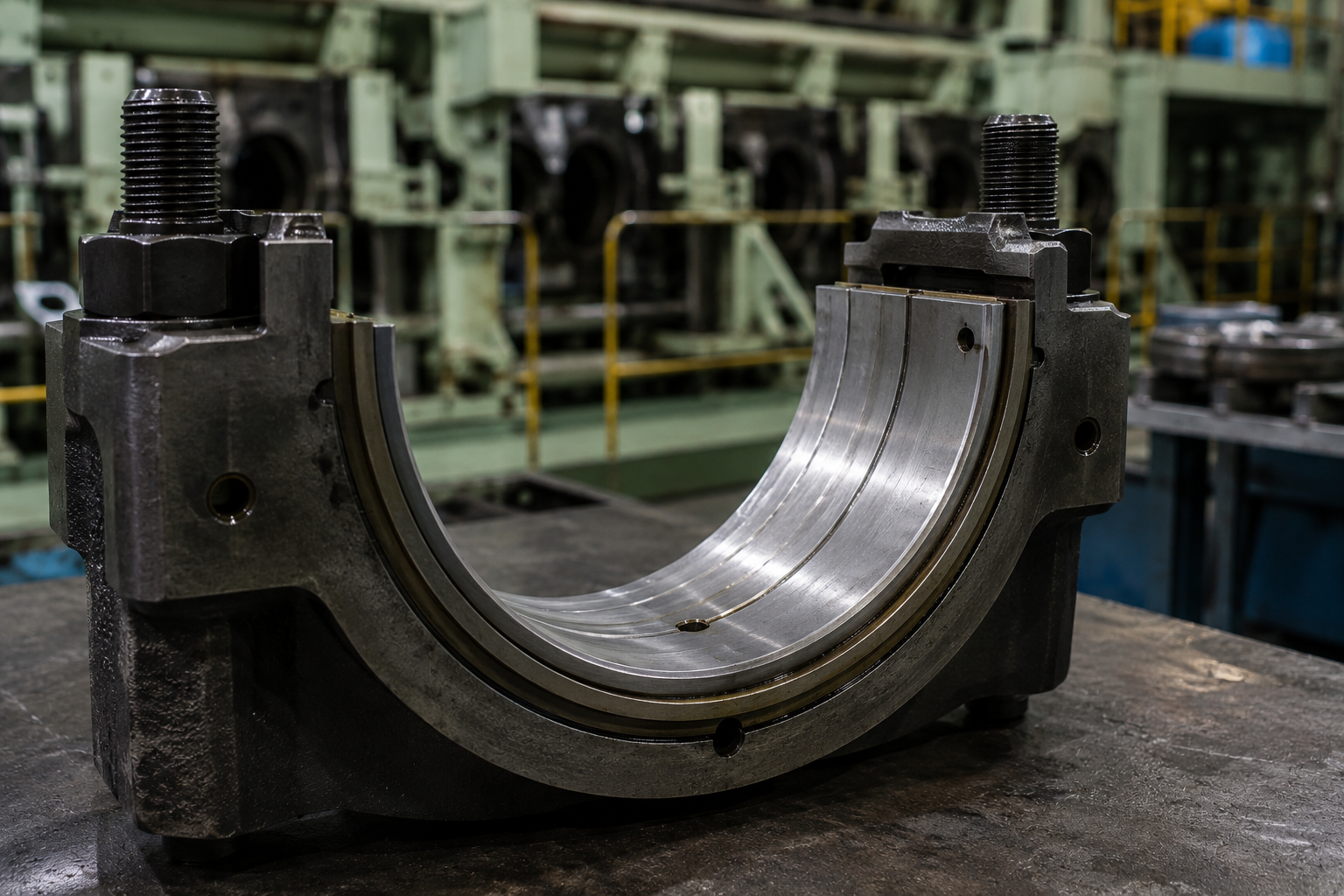
A main bearing normally consists of upper and lower bearing shells fitted into a bearing housing, saddle, cap, girder or engine block arrangement depending on engine design. The shell may include a steel backing, lining or intermediate layer, overlay where applicable, oil grooves, oil holes, locating features and a finished running surface.
The shell back supports heat transfer and load transmission into the housing. The running surface carries the oil film and is the area where polishing, wiping, scoring, fatigue, pitting, corrosion or embedded-particle damage may be seen. Oil grooves and holes distribute lubricating oil to the bearing surface and, in some designs, onward to other crankshaft oil passages.
Actual construction varies by manufacturer, engine type, bearing material and bearing supplier. The terms upper shell, lower shell, overlay, lining, backing, crush, clearance and seating should therefore be applied to the actual bearing design and maker documentation for the engine being inspected.
Hydrodynamic lubrication, clearance and seating
Main bearings normally operate with hydrodynamic lubrication. As the crankshaft rotates, oil is drawn into the bearing clearance and forms a load-carrying film that separates the journal from the bearing surface. This oil film depends on oil supply, viscosity, temperature, shaft speed, load, surface condition and correct clearance.
Bearing clearance is necessary for oil-film formation and oil flow, but both excessive and insufficient clearance can create problems. Too much clearance may reduce oil-film control and increase leakage or impact loading. Too little clearance may restrict oil-film formation, increase temperature or create metal-to-metal contact.
Bearing crush or interference, where specified by the maker, helps the shell seat firmly in the housing and maintain support and heat transfer. Clean shell seating, correct parts, correct orientation and undamaged housing surfaces are essential. Locating tabs or features are principally for positioning; they should not be treated as the only method preventing shell movement.
When should main bearings be inspected?
Main bearings should be inspected according to the applicable maker maintenance schedule and whenever operating evidence suggests possible bearing distress. Triggers include scheduled overhaul, crankcase inspection findings, high or unstable main-bearing temperature, abnormal lubricating-oil pressure, metallic debris in filters, abnormal oil analysis, crankshaft-deflection changes, abnormal vibration, knocking or unusual crankcase noise.
Inspection may also be required after suspected oil starvation, bearing alarms, grounding, collision, heavy structural events, foundation or chocking work, alignment work, repeated bearing problems or related crankshaft and connecting-rod findings. Actual inspection interval, opening scope, jacking method and acceptance criteria must follow engine-specific maker documentation and vessel safety procedures.
Pre-inspection assessment
- Confirm engine model, configuration, bearing number, bearing location and applicable maker documentation.
- Review running hours, previous bearing renewal records, previous clearance records and previous crankshaft-deflection readings.
- Review crankshaft main journal measurements, journal repair history and any previous NDT or polishing records.
- Check bearing-temperature trends, lubricating-oil pressure, oil temperature, oil-analysis results and filter or strainer findings.
- Review recent engine loading, manoeuvring, overload events, alarms, abnormal vibration, foundation work, alignment work and major vessel events.
- Prepare identification and recording so each shell remains traceable to its exact position, orientation and inspection condition.
Main-bearing inspection procedure overview
A main-bearing inspection should be controlled and documented. The general workflow is to open or remove components according to the maker procedure, identify the bearing position, preserve shell orientation, inspect the running surface and shell back, inspect the crankshaft main journal, verify oil supply paths, assess shell seating and housing condition, measure applicable clearances and record all findings.
Actual jacking, lifting, hydraulic tool use, bearing-cap handling, crankshaft support, turning gear operation and bearing removal procedures are engine-specific and safety-critical. They must be carried out according to the maker instruction book, vessel procedures, class requirements and the ship's permit-to-work system.
Bearing-shell running-surface inspection
The running surface should be assessed for overall appearance and local defects. Normal service appearance may include smooth polishing or light contact marks consistent with stable oil-film operation. Abnormal findings include wiping, smearing, scoring, embedded particles, overlay loss, fatigue cracking, pitting, flaking, corrosion, cavitation or erosion where relevant, heat discolouration, seizure damage, edge loading, local high spots and uneven axial or circumferential contact.
A wear pattern alone does not prove one root cause. For example, wiping may relate to oil starvation, excessive temperature, overload, incorrect clearance, contamination, misalignment or a combination of factors. Scoring may come from hard particles, bearing debris, journal defects or oil-passage contamination. Edge loading may point toward alignment, journal geometry, housing support or structural movement rather than a simple bearing-shell issue.
Main bearing wear pattern, possible causes and additional checks
| Wear pattern | Possible contributing causes | Additional checks |
|---|---|---|
| Normal polishing | Stable running contact and normal service wear | Record condition, compare with previous inspections and continue trend monitoring |
| Overlay wiping | Reduced oil film, oil starvation, high temperature, overload, incorrect clearance or contamination | Check oil supply, oil temperature, clearance, journal surface, load history and bearing-temperature trend |
| Heavy wiping or smearing | Severe oil-film loss, metal-to-metal contact, overload, misalignment or restricted oil supply | Inspect journal for transfer or heat marks, trace oil supply path and escalate repair assessment |
| Longitudinal scoring | Hard particles, abrasive contamination, bearing debris or journal defect | Inspect filters, strainers, oil cleanliness, oil holes, journal surface and previous component failures |
| Circumferential scoring | Rotational rubbing, oil starvation, debris dragged around the journal or surface defect | Check journal condition, oil grooves, clearance and evidence of overheating |
| Embedded particles | Soft bearing material trapping hard particles from oil contamination or component distress | Inspect lubricating oil, filters, strainers, tanks, purifier performance and debris source |
| Fatigue cracks | Cyclic loading, local stress, overload, poor support, material fatigue or alignment influence | Assess crack extent, bearing history, load history, journal geometry and maker criteria |
| Pitting or flaking | Fatigue, corrosion, cavitation or surface distress depending on appearance and location | Check oil condition, water ingress, loading, journal finish and material condition |
| Corrosion | Water ingress, degraded oil, acidic contamination or long idle exposure | Review oil analysis, water content, storage condition and crankcase environment |
| Overheating or discolouration | Insufficient oil film, high oil temperature, overload, insufficient clearance or seizure onset | Check bearing temperature trend, oil supply, clearance, journal heat marks and sensor accuracy |
| Edge loading | Misalignment, journal taper, housing distortion, uneven bearing support or crankshaft alignment change | Check crankshaft deflection, journal geometry, housing contact and alignment records |
| Localised wear | High spot, debris, poor seating, local journal defect or housing contact issue | Inspect shell back, housing, journal surface and oil-film evidence |
| Uneven contact | Support change, bedplate/foundation influence, incorrect assembly or journal geometry issue | Compare bearing contact, deflection history, clearance and foundation/alignment condition |
| Shell-back fretting | Relative movement, poor seating, insufficient support, contamination beneath shell or housing issue | Inspect housing surface, shell back, crush/interference where specified and assembly history |
| Bearing seizure | Severe lubrication failure, extreme overheating, overload or rapid oil-film collapse | Stop root-cause assumptions; inspect bearing, journal, oil system, alarms, load history and collateral damage |
Bearing wiping and smearing
Bearing wiping is displacement or removal of surface material after the hydrodynamic oil film becomes inadequate. Smearing is related surface dragging or material movement caused by abnormal contact and heat. These findings usually indicate that the bearing did not have stable separation from the journal at some point in operation.
Contributing factors can include insufficient oil supply, high oil temperature, degraded viscosity, excessive load, incorrect clearance, contamination, poor shell seating, journal defects or alignment problems. Renewing the shell without checking oil supply and crankshaft main journal condition can leave the original failure mechanism in place.
Scoring and embedded-particle damage
Scoring appears as grooves or scratches on the bearing running surface. It can be caused by hard contaminants, metallic debris from another failure, damaged oil passages, dirty assembly conditions or defects on the crankshaft journal. Softer bearing materials may embed particles, which can protect the journal in some cases but also proves that contamination has entered the bearing system.
Engineers should check lubricating-oil cleanliness, filters, strainers, purifier operation where fitted, oil sampling records, bearing debris, previous component damage, oil grooves, oil holes and the journal surface. A scored shell should prompt a search for the particle source, not only a shell replacement.
Overlay fatigue, cracking, pitting and flaking
Overlay fatigue and cracking may result from repeated cyclic loading, excessive local stress, poor support, overload, alignment changes or material fatigue. Pitting and flaking may involve surface fatigue, corrosion or other surface distress depending on appearance, depth and location.
The depth and extent of damage must be assessed against maker and bearing-supplier criteria where applicable. Visual appearance alone is not enough to decide whether a bearing can remain in service, be reused after inspection or must be renewed.
Edge loading and uneven contact
Edge loading is concentrated contact toward one side or end of the bearing shell. Uneven contact may appear as heavy polishing, wiping or local wear in a limited area while other areas carry less load. This pattern can indicate misalignment, journal taper, bearing housing distortion, incorrect bearing support, shell seating issues, structural movement or crankshaft alignment changes.
The response should extend beyond the shell. Check crankshaft deflection, main-journal geometry, bearing clearance, shell-back contact, housing condition, bedplate support, foundation condition and historical alignment information before recommending corrective work.
Bearing-shell back and seating inspection
The shell back should be inspected for fretting, polished areas, corrosion, movement marks, poor contact, indentation and contamination. Fretting or polished marks on the back can indicate relative movement between shell and housing, inadequate support, damaged mating surfaces or incorrect seating.
Housing condition, bearing crush or interference where maker-specified, mating-surface cleanliness, correct part selection and assembly history should be considered. Dirt, burrs, corrosion or incorrect components beneath the shell can distort support and affect heat transfer.
Bearing crush and housing condition
Bearing crush or interference is the designed fit condition that helps hold the shell securely in the housing after assembly. It supports load transfer, shell stability and heat flow from the running surface through the backing into the engine structure. The required condition is design-specific and must not be replaced by a universal value.
Damaged housing surfaces, corrosion, indentation, contamination beneath the shell, incorrect components or improper seating can affect bearing performance even when the running surface initially appears acceptable. Housing and saddle condition should be treated as part of the bearing inspection, especially after fretting, repeated failures or edge loading.
Crankshaft main-journal inspection
The crankshaft main journal should be inspected whenever the bearing is opened. Important findings include scoring, polishing, ridging, pitting, corrosion, bearing-material transfer, heat marks, oil-hole condition, sharp edges, surface roughness and dimensional condition.
Where maker-specified, engineers should measure journal diameter, ovality and taper at defined positions. A new main bearing should not simply be fitted against a damaged, contaminated, overheated or geometrically unacceptable journal. Journal condition directly affects oil-film formation and the life of the replacement bearing.
Main-bearing clearance
Main-bearing clearance is the controlled space between the crankshaft journal and the bearing surface. It allows oil flow and oil-film formation while maintaining the crankshaft in the intended operating position. Clearance should be measured by maker-approved methods and recorded by bearing position.
Measurement methods may include direct dimensional measurement, lead-wire or soft-wire methods, or other engine-specific procedures depending on engine design. No single method should be assumed for every engine. Readings must be compared with the applicable manufacturer limits, previous records and the condition of the shell and journal.
Bearing clearance trending
A single clearance reading can be useful, but trend changes are often more informative. Increasing clearance may suggest wear, shell distress, journal condition changes or support issues. Reduced or unexpectedly low clearance may indicate incorrect components, assembly problems, distortion or measurement error.
Clearance trends should be reviewed together with running-surface condition, journal measurements, bearing-temperature history, crankshaft-deflection data, lubricating-oil condition and any recent overhaul or alignment work.
Lubricating-oil supply and oil-film assessment
Lubricating-oil supply should be checked as a complete path, not only as a pressure reading. Review oil pressure, oil temperature, viscosity condition, contamination, water ingress where relevant, oil degradation, filters, strainers, oil grooves, oil holes, supply passages and signs of oil starvation on the shell.
The hydrodynamic oil film depends on load, speed, viscosity, clearance, temperature and surface condition. High oil temperature can reduce effective viscosity, contamination can damage the surface, blocked passages can starve the bearing and excessive clearance can change oil leakage and film behaviour. Practical diagnosis should combine operating trends with physical inspection.
Bearing temperature and overheating
Main-bearing temperature trends can provide early warning of changing bearing condition, lubrication problems, load changes, clearance issues, sensor faults or alignment influences. A high-temperature alarm should be investigated quickly but should not automatically be assumed to prove bearing failure without supporting evidence.
Checks should include local and remote temperature indication where available, oil pressure, oil temperature, oil flow path, bearing clearance, crankshaft journal condition, recent load changes, crankshaft deflection history and the accuracy or condition of the temperature sensor.
Main-bearing condition versus crankshaft deflection
Bearing wear, bearing-height changes, support changes and alignment movement can influence crankshaft deflection readings. Historical crankshaft-deflection trends may support diagnosis when main-bearing condition is being assessed.
Crankshaft deflection does not directly identify one failed bearing by itself. It must be interpreted together with bearing inspection findings, clearance measurements, journal condition, vessel loading state, engine temperature, bedplate/foundation information and previous readings.
Main-bearing alignment, bedplate and foundation relationship
On large low-speed engines, bearing support is influenced by the bedplate, bearing saddles, chocking, foundation bolts, hull structure and vessel loading. Structural movement, bearing support changes, incorrect bearing height, foundation problems or hull deflection may contribute to uneven bearing loading.
Bearing adjustment or alignment correction should never be recommended solely from visual wear patterns. Proper measurement, maker-approved alignment assessment and review of crankshaft deflection and foundation data are required before deciding corrective actions.
Vessel loading and hull influence
Large vessel hulls flex under loading, ballast condition and sea state. That hull deformation can influence machinery alignment and bearing loading, which is why crankshaft-deflection records and related measurements should document vessel loading condition, engine temperature condition and measurement setup where required by the maker.
Comparing readings taken under very different vessel states can mislead diagnosis. The value of trend records depends on consistent measurement conditions and clear documentation.
Key main-bearing measurements and checks
| Component/Area | Measurement or Check | Why It Is Checked | Possible Significance of Abnormal Findings |
|---|---|---|---|
| Bearing running surface | Visual inspection of polishing, wiping, scoring, fatigue and corrosion | Assesses oil-film condition and contact pattern | May indicate lubrication issue, contamination, overload, misalignment or material distress |
| Bearing clearance | Maker-approved clearance measurement | Confirms controlled oil-film space | Excessive or insufficient clearance can affect lubrication and temperature |
| Shell back | Fretting, polishing, corrosion and movement marks | Checks support and seating | May indicate poor seating, housing issue or shell movement |
| Shell seating/contact | Contact pattern and housing cleanliness | Confirms support and heat transfer | Poor contact can distort loading and temperature |
| Bearing crush/interference | Check where maker-specified | Maintains shell stability | Incorrect condition may permit movement or poor support |
| Housing or saddle | Surface damage, corrosion, indentation and distortion evidence | Checks structural support | May contribute to repeated bearing distress |
| Main-journal diameter | Maker-specified dimensional measurement | Confirms journal size | Wear or repair history may affect clearance |
| Journal ovality | Out-of-roundness where specified | Checks geometry for oil-film stability | Abnormal ovality can create uneven loading |
| Journal taper | Diameter change along journal length | Checks axial geometry | Abnormal taper can cause edge loading |
| Journal surface condition | Scoring, ridging, pitting, heat marks and transfer | Checks compatibility with bearing surface | Damaged journal can rapidly damage a renewed shell |
| Oil grooves, holes and passages | Cleanliness and blockage check | Confirms oil delivery | Restriction can cause starvation or local overheating |
| Bearing-temperature history | Trend review | Finds early changes | Rising trend may indicate lubrication, clearance, load or alignment issue |
| Crankshaft-deflection trend | Compare historical readings | Supports alignment and support assessment | Changes may indicate support, bearing or foundation changes |
| Alignment observations | Review foundation, chocking and recent structural work | Links bearing loading to machinery support | Abnormal findings may require maker-approved alignment assessment |
Measurement accuracy and documentation
Reliable bearing assessment depends on calibrated measuring tools, clean measuring surfaces, correct bearing identification, maker-specified measuring positions, consistent engine condition and repeatable methods. Measurements should record the bearing number, shell position, measurement method, tool used, engine condition and comparison with previous records.
Photographs should be taken before aggressive cleaning where damage evidence may be lost. Running-surface condition, shell-back condition, journal findings, clearance readings, oil findings and temperature history should be documented together so the technical conclusion is traceable.
Common main-bearing problems and failure modes
Common main-bearing problems include wiping, smearing, scoring, abrasive wear, contamination damage, embedded particles, overlay fatigue, pitting, flaking, corrosion, overheating, seizure, edge loading, shell-back fretting, poor seating, excessive clearance, insufficient clearance, lubrication failure and repeated bearing distress.
Each problem should trigger a next inspection step. Wiping leads to lubrication, temperature, clearance and journal checks. Scoring leads to contamination and journal checks. Fretting leads to seating, housing and crush/interference checks. Edge loading leads to alignment, journal geometry and support checks. Repeated distress should be treated as a system problem until proven otherwise.
Symptom, possible cause and inspection
| Symptom | Possible cause | Inspection |
|---|---|---|
| High bearing temperature | Oil starvation, overload, clearance issue, misalignment or sensor fault | Check temperature trend, sensor accuracy, oil supply, clearance, shell surface and journal condition |
| Rapidly increasing bearing temperature | Developing oil-film failure, blocked oil path, overload or seizure onset | Reduce risk according to vessel procedure and inspect bearing, journal and lubrication path |
| Overlay wiping | Loss of oil film, contamination, high temperature, overload or clearance problem | Check oil quality, oil supply, clearance, journal surface and load history |
| Heavy shell scoring | Hard particles, bearing debris, dirty oil or journal defect | Inspect filters, strainers, oil passages, debris source and journal surface |
| Embedded particles | Contaminated oil or debris from another component | Check oil cleanliness, filters, purifier operation and previous failures |
| Fatigue cracking | Cyclic overload, local stress, poor support, material fatigue or alignment issue | Assess crack extent, loading, bearing support and maker criteria |
| Shell-back fretting | Relative movement, poor seating, housing damage or insufficient support | Inspect shell back, housing, mating surfaces and crush/interference where specified |
| Edge loading | Misalignment, journal taper, housing distortion or support change | Check crankshaft deflection, journal geometry, clearance and foundation/alignment history |
| Uneven wear | Incorrect seating, bedplate/foundation influence, journal geometry or load distribution issue | Inspect shell contact, journal dimensions, housing condition and alignment data |
| Excessive bearing clearance | Wear, incorrect component, journal wear or previous damage | Measure clearance by maker method and compare with records and maker limits |
| Insufficient bearing clearance | Incorrect component, assembly issue, distortion or measurement error | Verify part number, seating, journal dimensions and measurement method |
| Metallic debris in oil/filter | Bearing distress, journal damage or another component failure | Identify debris type/source, inspect affected bearings, journals and oil system |
| Low lubricating-oil pressure | Pump issue, viscosity/temperature issue, leakage, relief valve or excessive clearance | Check oil level, pump, filters, relief valve, oil temperature and bearing clearances |
| Crankshaft journal scoring | Contamination, oil starvation, bearing debris or oil-hole edge issue | Inspect journal, oil holes, bearing shell, filters and oil cleanliness |
| Heat marks on shell or journal | Overheating, oil-film collapse, overload or seizure event | Check lubrication, clearance, journal condition and alarm history |
| Abnormal crankshaft deflection | Bearing support change, alignment movement, foundation influence or structural condition | Compare historical readings and inspect bearings, journals and foundation/alignment data |
| Abnormal vibration | Bearing distress, crankshaft issue, alignment problem or cylinder/load imbalance | Separate combustion and mechanical causes; inspect bearings, crankshaft and alignment |
| Knocking or crankcase noise | Excessive clearance, bearing damage, lubrication problem or mechanical looseness | Investigate promptly; inspect bearing, journal, oil pressure and related components |
| Repeated main-bearing failure | Unresolved lubrication, journal, alignment, housing, assembly or loading issue | Conduct root-cause investigation before renewing another shell |
Root-cause investigation after main-bearing damage
- Document the damaged bearing before cleaning, including position, orientation and photographs.
- Inspect the bearing running surface and shell back for wiping, scoring, fretting, fatigue, heat marks and seating evidence.
- Inspect the crankshaft main journal for scoring, transfer, heat marks, oil-hole condition and dimensional findings where maker-specified.
- Verify bearing clearance and relevant journal dimensions using maker-approved methods.
- Trace the lubricating-oil supply path from system pressure to filters, strainers, grooves, holes and local passages.
- Review oil pressure, oil temperature, oil analysis, contamination and debris history.
- Compare bearing-temperature records, crankshaft-deflection records, recent loading and recent maintenance.
- Consider alignment, bedplate, foundation, chocking, hull influence, housing support and repeated failure history.
- Determine the likely root cause and repair scope before returning the bearing position to service.
Bearing finding and possible engineering response
| Bearing finding | Possible engineering response |
|---|---|
| Normal service wear | Document, compare with previous records and continue monitoring |
| Minor polishing | Record condition and verify there is no abnormal temperature, debris or clearance trend |
| Scoring | Investigate contamination, oil passages, filters and journal condition before deciding renewal scope |
| Embedded debris | Identify debris source and inspect lubricating-oil cleanliness and related components |
| Overlay deterioration | Assess extent against maker criteria and check load, clearance and lubrication history |
| Wiping | Inspect oil supply, clearance, temperature history, journal condition and alignment influence |
| Fatigue cracking | Escalate for maker or specialist assessment where required and review loading/support condition |
| Shell-back fretting | Inspect housing, seating, mating surfaces and crush/interference where maker-specified |
| Excessive clearance | Check shell and journal wear, compare records and follow maker criteria for correction |
| Journal damage | Assess journal repair or specialist reconditioning before fitting a new shell |
| Severe overheating | Investigate lubrication failure, collateral damage and maker-approved repair requirements |
Reuse versus renewal
Bearing-shell reuse or renewal decisions must follow maker requirements, measured condition, running-surface findings, shell-back findings, journal condition, running hours and service history. Severe wiping, cracking, overheating, seizure marks, abnormal fretting or other damage may require renewal and further investigation according to engine-specific criteria.
A bearing should not be reused solely because damage appears visually minor. The decision should account for measurements, trend records, operating symptoms, oil findings and the consequences of repeat failure.
Reassembly considerations
- Confirm that the crankshaft journal is acceptable before installing or refitting the bearing shell.
- Clean the housing, seating surfaces, oil grooves, oil holes and local passages according to maker requirements.
- Verify the correct bearing part number, bearing position, shell orientation and locating features.
- Ensure the shell is correctly seated and specified running surfaces are lubricated as required.
- Install bearing caps, girders or related components using maker-approved tightening, hydraulic and safety procedures.
- Verify bearing clearance, crankshaft turning/free movement and oil supply condition according to the instruction book.
- Record all measurements, parts fitted, observations and post-maintenance checks.
Post-maintenance monitoring
After main-bearing inspection, renewal or related crankshaft work, monitoring should confirm lubrication, oil pressure, oil temperature, bearing temperature, abnormal noise, abnormal vibration and crankcase observations. Initial start and load-up should follow vessel and maker procedures.
Follow-up inspections or measurements may be required depending on the repair scope, bearing findings and maker guidance. Temperature and oil trends after return to service are often as important as the single post-maintenance inspection result.
Low-speed two-stroke versus medium-speed and four-stroke engines
Large low-speed two-stroke engines commonly have massive crankshafts supported in a bedplate structure, with crankshaft deflection and foundation condition playing an important role in bearing assessment. Access, bearing handling and alignment interpretation are heavily maker-specific.
Medium-speed and high-speed four-stroke engines may have different bearing caps, block structures, bearing materials, oil-routing arrangements, crankshaft stiffness, firing loads and inspection procedures. The concepts of oil film, clearance, seating, journal condition and contamination still apply, but procedures and acceptance criteria must be taken from the relevant engine documentation.
FAQ
What should be checked during a marine engine main-bearing inspection?
Check bearing running surface, shell back, seating, clearance, crankshaft journal condition, oil grooves, oil holes, temperature history, lubrication condition, crankshaft-deflection trend and related alignment information.
What does bearing wiping look like and what causes it?
Wiping usually appears as smeared, dragged or displaced bearing surface material. It can be caused by loss of oil film, oil starvation, high temperature, overload, contamination, incorrect clearance or alignment influence.
What causes scoring on a main bearing?
Scoring is commonly linked to hard particles, metallic debris, dirty oil, damaged oil passages or crankshaft journal defects. The debris source should be traced before repair is closed.
What do embedded particles indicate?
Embedded particles indicate contamination or debris in the oil path. They may come from dirt ingress, previous component damage, bearing debris, poor cleaning or oil-system problems.
What causes fretting on the back of a bearing shell?
Shell-back fretting may indicate relative movement, poor seating, inadequate support, damaged housing surfaces, contamination beneath the shell or incorrect assembly.
What is main-bearing clearance?
Main-bearing clearance is the controlled space between the crankshaft journal and bearing surface. It allows lubricating oil flow and hydrodynamic oil-film formation.
What happens if bearing clearance is too large or too small?
Excessive clearance may reduce oil-film control, increase leakage and contribute to impact loading. Insufficient clearance may restrict oil-film formation and increase temperature or rubbing risk.
What is bearing crush?
Bearing crush or interference is the designed fit that helps the shell seat firmly in the housing. Actual requirements are engine and bearing-design specific.
Why is crankshaft journal condition important?
A damaged journal can quickly damage a new bearing. Scoring, taper, ovality, heat marks, material transfer or blocked oil holes can affect oil-film formation and bearing life.
Can misalignment cause uneven bearing wear?
Yes. Alignment, bearing support, journal geometry, bedplate condition and foundation movement can concentrate load and create uneven contact or edge loading.
Can crankshaft deflection indicate a main-bearing problem?
Crankshaft deflection trends can support diagnosis of support or alignment changes, but they do not directly identify one failed bearing. They must be interpreted with bearing inspection and measurements.
What causes high main-bearing temperature?
Possible causes include oil starvation, high oil temperature, reduced viscosity, overload, clearance problems, misalignment, journal damage, bearing distress or sensor issues.
What should be checked after a main-bearing failure?
Check the damaged shell, shell back, housing, crankshaft journal, bearing clearance, oil supply path, filters, oil analysis, temperature trend, crankshaft deflection and alignment/foundation history.
Can a marine engine main bearing be reused?
Reuse depends on maker requirements, measured condition, visual findings, running hours, journal condition and operating history. There is no universal reuse rule.
How are main-bearing problems prevented?
Prevention depends on clean lubricating oil, stable oil pressure and temperature, correct assembly, maker-specified clearances, acceptable journal condition, alignment control, trend monitoring and timely investigation of abnormal alarms or debris.
Measurements and acceptance limits
Condition assessment should be based on recorded measurements, visual findings, operating symptoms, and the applicable maker documentation. Acceptable limits should be confirmed against the applicable manufacturer's manual and engine-specific technical documentation.
Need technical assistance?
If inspection, overhaul, troubleshooting, workshop repair, or onboard attendance is required, Dieselmech Group can review the symptoms, engine details, operating history, and available measurements before recommending the next practical step. Contact us at +65 6334 1855, email sales@dieselmech.com.sg, or submit an enquiry through the Contact Us page.
Technical note
This article is for general technical information. Actual procedures, limits, clearances, pressures, temperatures, torque values, and renewal criteria depend on the engine model, configuration, maker revision, service bulletin, vessel procedures, and class requirements. Manufacturer manuals and vessel safety procedures take precedence. Safety-critical work should be carried out by appropriately qualified personnel.
Published by Dieselmech Group Technical Team. For advice on a specific engine or fault, contact our marine engineers.