
-DQG-c1Ek.png)
Technical Article
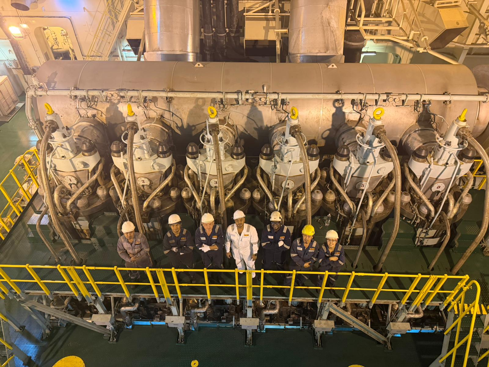
MAN B&W ME-C Exhaust Valve Actuation System Explained
On MAN B&W ME-C engines, exhaust-valve opening is electronically determined by the Engine Control System and executed using hydraulic or servo-oil energy from the Hydraulic Power Supply. On many configurations, valve closing is supported by an air-spring arrangement. The exact control architecture varies between engine generations, Mark versions, bore sizes and control-system revisions, so engineers must confirm whether the engine uses FIVA-based combined fuel injection and valve actuation, separate ELVA or an equivalent electro-hydraulic exhaust-valve control arrangement before diagnosing faults.
What is the ME-C exhaust-valve actuation system?
The ME-C exhaust-valve actuation system is the electronically controlled and hydraulically executed system that opens the exhaust valve on a MAN B&W ME-C low-speed two-stroke engine at the required point in the engine cycle. The Engine Control System calculates the timing according to engine condition and crank-angle reference, then cylinder-specific control hardware commands the relevant electro-hydraulic equipment.
The electronic command does not lift the valve by itself. Hydraulic or servo-oil energy from the Hydraulic Power Supply is directed to an exhaust-valve actuator, which converts pressure into mechanical movement of the exhaust-valve spindle. On many ME-C configurations, the exhaust valve closes through an air-spring arrangement that provides pneumatic closing force and helps return or hold the spindle on its seat.
ME-C exhaust-valve control architecture is not universal. Some engines use FIVA-based combined fuel injection and valve actuation, while other generations or configurations use separate ELVA or equivalent electro-hydraulic exhaust-valve control arrangements. Component names, control units, feedback signals and diagnostic functions differ across ME-C generations, Mark versions, bore sizes and control-system revisions. The installed engine instruction book, control-system documentation and service bulletins always take priority.
Although timing is electronically controlled, the exhaust valve remains a physical mechanical and hydraulic assembly. Components such as the spindle, seat, cage or housing, guide, actuator or piston arrangement, hydraulic passages, seals, air spring and related connections can suffer wear, deposits, sticking, leakage, erosion, burning, corrosion or misalignment. A MAN B&W ME-C exhaust valve alarm therefore has to be investigated across the electronic, hydraulic, pneumatic and mechanical chain.
ME-C versus MC-C exhaust-valve control
On MC-C engines, exhaust-valve operation is based on mechanically timed camshaft-driven actuation. Cam profiles, roller gear, linkages and hydraulic or mechanical valve gear translate crankshaft rotation into exhaust-valve movement. Troubleshooting therefore focuses strongly on mechanical timing, cam and roller condition, linkage movement, actuator condition and conventional valve inspection.
On ME-C engines, the conventional exhaust-valve timing cam function is replaced by electronically commanded electro-hydraulic control. This gives the control system greater flexibility over exhaust-valve timing compared with a fixed cam profile, but it also changes the diagnostic approach. Engineers must evaluate control commands, crank-angle reference, cylinder-control hardware, FIVA or ELVA status where applicable, HPS pressure, servo-oil cleanliness, actuator response, air-spring closing and the physical condition of the valve.
System architecture and control-flow overview
A useful conceptual chain for ME-C exhaust valve actuation is: engine speed/load demand plus crank-angle information -> Engine Control System -> cylinder-specific control command -> CCU or related control hardware -> FIVA, ELVA or equivalent control component -> HPS hydraulic supply -> exhaust-valve actuator -> spindle opens -> air spring or closing force returns valve to seat -> feedback, alarm or performance response.
That chain contains different types of energy and information. Electronic signal flow includes demand, crank-angle reference, control commands, status signals and alarms. Hydraulic or servo-oil flow is the working energy used to open the valve. Pneumatic air-spring energy is used on applicable configurations to support closing and seating. Mechanical movement is the actual actuator and spindle movement that opens and closes the exhaust passage.
Keeping these flows separate prevents poor diagnosis. A correct electronic command does not prove that hydraulic pressure reached the actuator. Stable HPS pressure does not prove that the cylinder-specific control component moved correctly. An actuator movement indication, where fitted, does not by itself prove that the spindle, seat and cage are in acceptable physical condition.
How one exhaust-valve event happens
- The control system determines the required exhaust-valve opening timing from engine operating condition and approved control logic.
- Crank-angle or timing-reference information provides the position reference needed for repeatable cylinder-specific timing.
- Cylinder-specific control hardware issues the command to the relevant FIVA, ELVA or equivalent electro-hydraulic equipment.
- The control component directs pressurised hydraulic or servo oil from the HPS toward the exhaust-valve actuator.
- Hydraulic force moves the actuator and exhaust-valve spindle away from the seat.
- Exhaust gas leaves the cylinder during the required exhaust period.
- The hydraulic command changes to end the opening event; hydraulic pressure is relieved, redirected or controlled according to the installed design.
- The air spring and other closing forces return the spindle toward the seat on applicable configurations.
- Correct seating completes the cycle and allows the cylinder to seal for the next compression and combustion process.
Engine Control System and cylinder-control role
The Engine Control System calculates when the exhaust valve should open and close based on crank-angle position, engine speed, load demand, operating mode, safety status and the control strategy approved for that engine. The ECS does not create the mechanical lifting force. It issues electronic commands that downstream hardware converts into hydraulic and mechanical action.
Cylinder Control Units, ECU/MPC-based hardware, actuator-control units or related modules may be involved depending on control-system generation. In general terms, engine-level hardware processes overall operation, cylinder-specific hardware executes cylinder commands, and monitoring functions record status, deviations and alarms. The names and division of responsibility vary, so engineers should use the actual maker documentation for the installed engine.
Protected settings, control algorithms, bypasses and safety logic are outside the scope of this guide. Diagnosis should use authorised displays, alarm history, event chronology, maker-approved tests and vessel procedures.
Crank-angle and timing reference
Accurate crankshaft-position information is essential because the exhaust-valve event must occur at the correct point in the engine cycle. If the control system cannot trust the crank-angle or timing-reference signal, it may generate exhaust-valve timing symptoms, valve-control alarms, cylinder-performance deviations or permissive restrictions depending on the installed control logic.
A timing-reference fault can look like a valve-control problem because the commanded event depends on angular position. Engineers should review alarm chronology, sensor plausibility, wiring, connectors and control-unit status before assuming the exhaust-valve actuator or FIVA/ELVA component has failed.
Hydraulic Power Supply relationship
The Hydraulic Power Supply provides the pressurised hydraulic or servo oil used as the energy source for exhaust-valve opening. The HPS does not decide valve timing; it supplies the working medium that lets the commanded electro-hydraulic equipment move the actuator.
Insufficient HPS pressure, unstable pressure, restricted filters, contaminated oil, internal leakage, accumulator issues where fitted, pump or control problems, and abnormal drain or return conditions can influence actuator response. HPS problems may appear as slow response, repeated exhaust-valve alarms, unstable cylinder behaviour, pressure alarms or multiple cylinders showing similar symptoms.
Because the HPS is a common source, a shared hydraulic-supply issue can affect more than one cylinder. A fault seen on only one unit may still involve hydraulic pressure locally, but it often points more strongly toward that cylinder's FIVA or ELVA, actuator, air spring, spindle, guide, seat, wiring or feedback path.
HPS versus cylinder-specific diagnostic reasoning
| Observation | Diagnostic direction | Inspection focus |
|---|---|---|
| Several cylinders show similar actuation abnormalities | Common hydraulic supply, control power, timing reference or shared control issue may deserve early attention | HPS pressure stability, filters, oil condition, alarms, common sensors, control-unit status and power supply |
| One cylinder repeatedly alarms | Cylinder-specific control or mechanical issue becomes more likely | FIVA/ELVA for that unit, actuator, spindle freedom, air spring, feedback device, wiring and valve seat condition |
| HPS pressure alarm appears before valve alarms | Valve symptoms may be secondary to hydraulic supply condition | HPS pumps, pressure regulation, filters, leakage, oil temperature and drain/return behaviour |
| Valve alarm appears with no common pressure issue | Local control, actuator, feedback or mechanical condition should be checked | Command/status data, connectors, control component response, actuator leakage, guide and seat condition |
FIVA exhaust-valve control principle
On engines using FIVA, the Fuel Injection and Valve Actuation component is involved in directing hydraulic energy for fuel injection and exhaust-valve actuation according to electronic commands. For the exhaust-valve side, the control signal initiates internal control movement that directs hydraulic flow to the actuator so the exhaust-valve spindle opens.
The practical relationship is command -> control movement -> hydraulic flow -> actuator movement -> valve movement. Faults may occur at any stage. Sticking, contamination, internal leakage, slow response, wiring faults or command/feedback mismatch can create exhaust-valve symptoms. Engineers should not assume every FIVA-related alarm means the FIVA must be replaced; the hydraulic supply, oil cleanliness, actuator, air spring and mechanical valve condition must also be considered.
This article does not provide invasive FIVA repair steps, protected calibration values or bench-setting procedures. Those must follow maker instructions and workshop requirements.
ELVA operating principle
On ME-C generations or configurations using Electronic Exhaust Valve Actuation, ELVA controls the hydraulic actuation of the exhaust valve according to the electronic command. ELVA should be understood as the exhaust-valve actuation function or arrangement for applicable engines, not as a universal component fitted to every ME-C engine.
ELVA is distinct from ELFI, which relates to Electronic Fuel Injection arrangements where applicable. Engineers should not mix FIVA, ELFI and ELVA terminology unless they have confirmed the actual engine generation and configuration. A fault described casually as an ELVA fault on one vessel may be arranged differently on another.
Exhaust-valve actuator and internal hydraulic leakage
The exhaust-valve actuator converts hydraulic pressure into linear movement of the exhaust-valve spindle. Depending on design, actuator piston and cylinder components, sealing elements, hydraulic supply, return or drain paths, mechanical connections and feedback arrangements may be involved.
Internal leakage, worn sealing surfaces, sticking, contamination, restricted oil passages or abnormal drain behaviour can influence actuator response. Excessive leakage may show as slow opening, inability to achieve expected movement, pressure instability, increased heat, abnormal drain or return flow, or repeated alarms rather than obvious external leakage.
Actuator inspection should assess surface condition, sealing evidence, leakage, oil passages, free movement and component identification according to maker requirements. Cleanliness is critical because fine hydraulic-control clearances can be damaged or blocked by particles.
Exhaust-valve spindle, guide, seat and cage
The spindle and guide remain conventional high-duty mechanical parts even though the timing command is electronic. Engineers should inspect spindle face and stem condition, guide wear, scoring, corrosion, deposits, overheating evidence, sticking marks, alignment and free movement.
Excessive guide wear can affect seating because the spindle may not return concentrically to the seat. Deposits, carbon build-up, thermal distortion, corrosion or scoring can increase friction and contribute to sluggish or incomplete movement. A control alarm can therefore originate from a mechanical restriction, not only from the electronic control component.
Seat and cage condition directly affects gas sealing, heat transfer and valve reliability. Inspection should look for burning, pitting, erosion, corrosion, deposit build-up, seat recession, uneven contact, gas-cutting marks, leakage tracks, cage or housing damage, cracks where applicable, and cooling or passage condition where the design includes relevant features.
Proper seat contact is required to seal combustion gas and to transfer heat from the valve head into the seat and surrounding structure. Poor contact can cause local overheating, burning, progressive leakage and high exhaust-gas temperature. Repeated seat damage should trigger root-cause investigation rather than repeated component renewal alone.
Valve rotator or rotation mechanism
Where fitted, a valve rotator or rotation mechanism promotes more even seat and face condition by reducing localised deposit build-up and thermal loading. Rotator arrangements vary by engine design and should be checked only according to the relevant instruction book.
A failed or ineffective rotation function can contribute to uneven contact, localised burning, deposits or abnormal wear. It should be considered during repeated exhaust-valve damage investigations where the installed design includes such a function.
Air spring operating principle and faults
On applicable ME-C exhaust-valve arrangements, the air spring provides pneumatic closing force and helps return or hold the exhaust valve on its seat after hydraulic opening. The general relationship involves air-spring pressure, sealing elements, piston or chamber arrangement and valve movement.
Air-spring condition is central to valve closing. Pressure loss, leakage, damaged seals, sticking components, contamination, supply-air problems or incorrect restoration after maintenance can contribute to slow closing, incomplete closing, valve-closing alarms, abnormal valve movement or poor seating.
The air spring contains stored pneumatic energy. Isolation, depressurising, dismantling, charging and testing must only be carried out by qualified personnel using maker-approved procedures, vessel safety precautions and lockout requirements. This article does not provide charging pressures or dismantling steps.
Valve opening versus valve closing faults
Opening problems are often investigated through the electronic and hydraulic side first: command data, cylinder-control hardware, FIVA or ELVA response, HPS pressure, servo-oil cleanliness, actuator leakage and mechanical freedom. Closing problems often bring the air spring, spindle and guide friction, actuator leakage, seat condition and feedback/instrumentation into sharper focus.
The distinction is useful but not absolute. A sticking spindle can affect both opening and closing. A hydraulic-control problem can delay opening and also prevent correct release or return behaviour. Air-spring problems may appear as closing faults but can also influence cylinder performance and repeated alarms.
Exhaust-valve timing, duration, lift and response
Electronic control allows the exhaust-valve opening and closing timing to be controlled according to the engine's operating strategy rather than being fixed only by a mechanical cam profile. Conceptually, this can support gas exchange, scavenging and engine optimisation across different operating conditions, but actual timing strategies are proprietary and engine-specific.
Valve movement must occur repeatably and within the maker-defined behaviour for the specific engine. Sluggish response, incomplete lift, delayed opening or delayed closing can affect exhaust-gas discharge, scavenging, compression conditions and combustion quality. Direct lift or position feedback should only be discussed where the installed configuration actually provides it; otherwise engineers infer behaviour from alarms, status information, cylinder performance and physical inspection.
Command, feedback and actual mechanical movement
ME-C exhaust-valve troubleshooting should distinguish four separate things: the electronic command sent by the control system, any available feedback or status signal, the hydraulic response of the actuator, and the actual mechanical condition of the spindle and seat. These are related but not identical.
A correct command does not prove the valve opened correctly. A feedback alarm does not automatically prove the electronic control component has failed. A leaking exhaust valve may have normal command history but poor seat contact. Conversely, a wiring or feedback issue may create an alarm even when the mechanical valve is not the primary fault. Diagnosis should compare command, feedback, hydraulic condition, air-spring condition and physical inspection evidence.
Relationship with cylinder performance
Exhaust-valve condition can influence exhaust-gas temperature, cylinder power, compression, peak-pressure or indicator information where available, scavenging, smoke, combustion quality and turbocharger or scavenge-system behaviour. Leakage, late opening, incomplete lift or poor closing may all appear as cylinder-performance changes.
Similar symptoms can also originate from fuel injection, poor atomisation, cylinder overload, liner or piston-ring condition, low compression, charge-air restriction, turbocharger condition or sensor issues. High exhaust temperature, low cylinder power or smoke should therefore be diagnosed as a cylinder-system problem, not automatically as an exhaust-valve fault.
High exhaust-gas temperature troubleshooting
High exhaust-gas temperature on an ME-C engine can be associated with exhaust-valve leakage, incorrect timing or response, late or incomplete opening, poor seating, fuel-injection problems, cylinder overload, poor atomisation, compression problems or charge-air and scavenge issues. The temperature reading alone does not identify the root cause.
A practical workflow is: review cylinder performance and exhaust-temperature trend -> review alarm and event chronology -> compare commanded or available valve status -> verify HPS pressure and common hydraulic condition -> inspect cylinder-specific FIVA or ELVA and actuator response -> check air spring -> inspect spindle, guide and seat condition -> verify fuel injection and combustion -> assess compression and scavenge condition.
Poor scavenging and exhaust flow
Delayed opening, incomplete opening, insufficient lift, deposits or mechanical restriction can reduce effective exhaust-gas discharge and disturb scavenging. The result may be high exhaust temperature, poor cylinder performance, smoke, abnormal pressure trends or unstable running depending on severity and operating condition.
Turbocharger, exhaust receiver, scavenge-air cooler, air-filter, charge-air pressure and scavenge-space condition can create similar symptoms. Engineers should compare exhaust-valve evidence with air-system and combustion evidence before deciding on repair scope.
Common ME-C exhaust-valve failure modes
Common failure modes include burnt spindle or seat, seat leakage, pitting, erosion, corrosion, excessive deposits, spindle sticking, guide wear, actuator leakage, hydraulic-control component sticking, contaminated servo oil, low or unstable HPS pressure, FIVA or ELVA faults where applicable, air-spring leakage, air-spring seal failure, control-signal or wiring faults, sensor or feedback problems and crank-angle or timing-reference faults.
Each problem should be treated as a diagnostic starting point rather than a final diagnosis. Engineers should ask what symptom is present, whether it is single-cylinder or common, which alarm came first, whether hydraulic supply is stable, whether command and feedback make sense, whether air-spring closing is healthy, and whether physical valve condition confirms the suspected cause.
Symptom, possible cause and inspection
| Symptom | Possible cause | Inspection |
|---|---|---|
| High exhaust-gas temperature | Exhaust-valve leakage, late or incomplete opening, poor fuel injection, overload, compression loss or scavenge-air issue | Compare trends, alarms, valve status, fuel equipment, compression and scavenge condition |
| Low cylinder power | Poor combustion, valve leakage, incomplete opening, actuator response issue, fuel problem or compression issue | Compare cylinder data, indicator information where available, exhaust valve, fuel valve and liner/ring condition |
| Cylinder imbalance | Fuel delivery difference, exhaust-valve response issue, compression variation, air distribution or control issue | Review cylinder balancing data, exhaust temperatures, alarms and mechanical findings |
| Exhaust-valve opening alarm | FIVA/ELVA response issue, actuator leakage, HPS pressure instability, wiring or feedback fault | Check alarm chronology, HPS condition, command/status data, connectors, actuator and valve movement |
| Valve-closing alarm | Air-spring pressure loss, leakage, sticking spindle, actuator release issue, seat obstruction or feedback fault | Inspect air spring, spindle freedom, actuator hydraulic condition, deposits, seat and instrumentation |
| Delayed opening | Control command issue, timing reference fault, slow hydraulic response, sticking control component or actuator restriction | Check crank-angle alarms, FIVA/ELVA status, HPS pressure, oil cleanliness and actuator movement |
| Incomplete opening or lift | Insufficient hydraulic force, actuator leakage, mechanical restriction, deposits or feedback issue | Inspect HPS pressure, actuator leakage, spindle/guide condition and available lift/status information |
| Slow closing | Air-spring weakness, seal leakage, spindle/guide friction, actuator leakage or deposit build-up | Check air spring, valve freedom, actuator return/drain behaviour and mechanical deposits |
| Failure to close | Air-spring failure, severe sticking, hydraulic release problem, mechanical obstruction or seat damage | Follow maker safety procedures; inspect air spring, actuator, spindle, guide and seat condition |
| Blow-by or leakage at valve | Burnt seat, worn spindle, deposits, poor contact, guide wear or combustion-related overheating | Inspect spindle face, seat contact, cage, leakage tracks, guide and fuel/combustion condition |
| Repeated seat burning | Poor seating, guide wear, cooling or heat-transfer issue, fuel-injection problem, deposits or incorrect response | Investigate valve contact, guide, timing/actuation, combustion quality and service history |
| Spindle sticking | Deposits, scoring, corrosion, guide wear, overheating, misalignment or lubrication/cleanliness issue | Inspect stem, guide, deposits, movement, temperature evidence and alignment |
| Abnormal actuator leakage | Seal wear, surface damage, internal leakage or contamination | Inspect drain/return behaviour, actuator surfaces, seals and oil cleanliness according to maker guidance |
| HPS pressure alarm | Low supply pressure, unstable pressure, filter restriction, pump/control issue or internal leakage | Check HPS pressure trend, filters, oil condition, leakage and whether several cylinders are affected |
| FIVA-related fault where applicable | Control movement issue, contamination, internal leakage, wiring fault or downstream actuator/mechanical issue | Confirm arrangement, review command/status data, inspect oil condition, actuator and valve condition |
| ELVA-related alarm where applicable | ELVA control issue, hydraulic response issue, wiring/feedback fault or exhaust-valve mechanical fault | Confirm engine generation, inspect control path, HPS, actuator, air spring and valve movement |
| Air-spring pressure loss | Leakage, damaged seals, supply-air issue, sticking components or incorrect restoration after maintenance | Inspect air-spring integrity and supply using maker-approved safety procedures |
| Unusual exhaust-valve noise | Loose, worn, sticking or leaking components; abnormal seating or actuator movement | Inspect valve gear, actuator, air spring, seat contact and alarm history |
| Excessive deposits | Poor combustion, fuel quality issue, oil carryover, low temperature operation, leakage or scavenging issue | Inspect valve, injector condition, scavenge condition and operating history |
| High cylinder-pressure trend related to timing where applicable | Timing/response deviation, fuel-injection change, load distribution or measurement issue | Compare indicator data, control status, fuel injection and exhaust-valve response |
| Poor scavenging | Delayed/incomplete exhaust opening, deposits, restriction, turbocharger or scavenge-air issue | Check valve movement, exhaust flow path, turbocharger and scavenge-air condition |
| Repeated valve-component failures | Root cause unresolved: seating, guide, actuation, air spring, combustion, load or maintenance issue | Perform system-level root-cause review before renewal |
Valve-closing fault diagnostic workflow
- Review the first relevant alarm and operating condition when the fault appeared.
- Check air-spring status, leakage evidence and supply-air condition according to maker procedures.
- Confirm spindle freedom and inspect for deposits, guide friction, corrosion or scoring.
- Assess actuator hydraulic release, internal leakage and drain or return behaviour.
- Review FIVA, ELVA or equivalent control-valve response and wiring or connector condition.
- Inspect seat damage, deposits or mechanical obstruction that could prevent proper seating.
- Check feedback or instrumentation plausibility where the configuration includes such signals.
Repeated exhaust-valve alarms
Repeated alarms should be investigated from the beginning of the event sequence, not only from the final alarm text. The first relevant alarm may point toward HPS pressure, timing reference, control-unit status, sensor plausibility, wiring, air-spring condition or actual valve response.
Before replacing components, engineers should review command/status data, wiring and connectors, HPS pressure and oil cleanliness, hydraulic response, air-spring behaviour, actuator leakage, spindle movement and physical valve condition. Replacing a control component while the underlying fault is contamination, air leakage or seat damage may lead to repeat failure.
Blow-by and exhaust-valve leakage diagnosis
Exhaust-valve blow-by usually requires inspection of the spindle face, seat contact, cage, guide condition, deposits, erosion, burning and leakage tracks. Leakage may produce high exhaust-gas temperature, low compression, poor combustion, poor starting, cylinder imbalance or visible damage during overhaul.
Combustion-related causes should also be considered. Poor atomisation, fuel-valve leakage, overload, low compression from other causes, deposits and scavenge-air problems can contribute to thermal loading and repeated exhaust-valve damage.
Inspection and overhaul scope
A proper inspection scope may include the valve spindle, seat, cage or housing, guide, actuator, hydraulic seals, air-spring components, control-valve interface, oil and air passages, rotator where fitted, related piping, connectors and feedback devices where fitted. The exact dismantling and overhaul procedure must follow the engine-specific MAN B&W/Everllence instruction book and vessel safety procedures.
Valve spindle inspection should cover head and face condition, stem condition, heat-affected areas, erosion, pitting, cracks, corrosion, deposits and maker-specified dimensions. Crack findings, severe burning or dimensional damage must be assessed against approved repair or renewal criteria.
Seat reconditioning and valve repair may include cleaning, grinding, lapping, machining, specialist welding or reconditioning, or renewal where permitted by the maker. Engineers should not assume that every damaged spindle or seat can be repaired. Seat recession, cracks, severe burning, loss of material, excessive guide wear or out-of-limit dimensions may require renewal or specialist assessment.
Guide and clearance assessment should consider stem-to-guide clearance, wear pattern, alignment and free movement without applying universal values. Air-spring inspection should consider sealing surfaces, piston or cylinder condition, leakage, contamination and maker-specified testing. Hydraulic actuator inspection should consider surface condition, sealing, leakage evidence, oil passages and free movement according to maker requirements.
Key exhaust-valve measurements and checks
| Component/Area | Measurement or Check | Why It Is Checked | Possible Significance of Abnormal Findings |
|---|---|---|---|
| Spindle and valve face | Visual condition, erosion, pitting, burning, cracks and maker-specified dimensions | Confirms sealing surface and material condition | Leakage, overheating, crack risk, renewal or specialist repair may be required |
| Seat condition and contact | Contact pattern, pitting, gas-cutting, recession and surface condition | Confirms gas sealing and heat transfer | Poor seating, blow-by, high exhaust temperature or repeated burning |
| Spindle/guide condition | Wear, clearance where applicable, scoring, corrosion, deposits and alignment | Confirms guided movement and seating alignment | Sticking, uneven seating, slow response or repeated seat damage |
| Lift or movement-related checks where maker-specified | Movement, response or lift indication according to installed design | Confirms expected valve behaviour | Delayed opening, incomplete lift or feedback mismatch |
| Actuator condition | Surface condition, sealing, leakage evidence and oil passage cleanliness | Confirms hydraulic force can be converted into movement | Internal leakage, sticking, slow response or pressure instability |
| Hydraulic leakage/response | Drain/return behaviour, response trend and leakage evidence | Identifies internal leakage not visible externally | Slow movement, heating, pressure drop or repeated alarms |
| Air-spring integrity | Leakage, sealing surfaces, supply condition and maker-approved test results | Confirms closing force availability | Slow closing, failure to close or closing alarms |
| Control-component response/status | FIVA/ELVA command and status data where available | Compares electronic command with control response | Command/feedback mismatch, wiring issue, sticking or hydraulic response problem |
| HPS pressure stability | Pressure trend, alarms, filters and oil condition | Confirms common hydraulic energy source | Multiple cylinder symptoms or poor actuator response |
| Cylinder-performance indicators | Exhaust temperature, power balance, indicator data where available and smoke/combustion observations | Connects valve condition to engine performance | Valve leakage, fuel problem, compression issue or scavenging problem |
Measurement interpretation and trending
Valve condition should be assessed using visual findings, measurements, alarm and event history, exhaust-temperature trends, cylinder-performance data, hydraulic condition, air-spring condition and service history. One isolated reading rarely explains the whole failure.
Trend direction matters. A value that remains within maker limits may still be important if it has changed rapidly since the previous inspection. A worn-looking part should still be measured and assessed against approved criteria before renewal decisions are made.
Root-cause investigation after repeated damage
Repeated spindle or seat burning should trigger investigation into valve seating and guide condition, timing and actuation response, air-spring operation, cooling or heat-transfer condition where applicable, fuel-injection quality, cylinder load, deposits, scavenge condition and combustion behaviour.
Simply renewing the damaged component may restore operation temporarily but leave the cause active. The repair report should connect physical findings with alarm history, operating trends, fuel equipment condition and hydraulic or pneumatic observations.
Before replacing FIVA, ELVA or the actuator
- Confirm the actual engine generation and whether the unit uses FIVA, ELVA or another equivalent arrangement.
- Review command, status and alarm history using authorised diagnostic functions.
- Inspect wiring, plugs, terminals, grounding and connector condition where applicable.
- Check HPS pressure stability, oil cleanliness, filters and contamination history.
- Look for hydraulic leakage, abnormal drain/return behaviour and actuator response issues.
- Check air-spring condition and valve-closing behaviour.
- Confirm spindle freedom, guide condition, deposits and seat condition.
- Follow maker diagnostic guidance before condemning an expensive electro-hydraulic component.
Single-cylinder versus common-system fault table
| Pattern | More likely cylinder-specific checks | More likely common-system checks |
|---|---|---|
| One unit high exhaust temperature with valve alarm | FIVA/ELVA for that unit, actuator, air spring, spindle, guide, seat and fuel valve | HPS trend and common alarms should still be reviewed |
| Several units show slow response | Check the worst unit for local damage after common checks | HPS pressure, oil cleanliness, filters, control power, timing reference and shared alarms |
| One unit blow-by evidence | Spindle, seat, guide, cage and combustion condition | Fuel quality or operating pattern if repeated across units |
| All or multiple units alarm after maintenance | Check disturbed local connections if work was cylinder-specific | Restored hydraulic/pneumatic supplies, common isolation valves, control power and sensor status |
| Intermittent alarms without physical damage | Connector condition, feedback device and local wiring | Control-unit status, crank-angle reference, HPS pressure fluctuations and electrical supply |
Post-overhaul and reassembly considerations
Post-overhaul work should confirm cleanliness, correct component identification, acceptable measurements, clean oil and air passages, correct seals and locking devices, spindle and seat assembly condition, guide condition, actuator assembly, air-spring assembly, and correct hydraulic and pneumatic connections. Tightening, adjustment and testing must follow engine-specific procedures.
This guide does not provide universal torques, HPS pressures, air-spring charging pressures, valve lifts, clearances, overhaul intervals or renewal limits. Those values must come from the applicable engine instruction book, ME control-system documentation, exhaust-valve documentation, service letters, vessel procedures and class requirements.
Post-maintenance verification
- Restore hydraulic and pneumatic supplies according to maker and vessel procedures.
- Check for oil, air and exhaust leakage after reassembly.
- Confirm control and alarm status before operation.
- Verify correct exhaust-valve response using maker-approved checks.
- Compare cylinder exhaust temperature, power and performance against sister units.
- Monitor carefully during controlled engine load-up and document any abnormal trend.
ME-C versus MC-C exhaust-valve actuation comparison
| Topic | ME-C | MC-C |
|---|---|---|
| Timing source | Electronically calculated command using crank-angle reference | Mechanically timed by camshaft profile and related gear |
| Opening energy source | Hydraulic or servo oil directed by electro-hydraulic control equipment | Mechanical/hydraulic actuation driven by camshaft-related mechanism |
| Closing arrangement | Often air-spring supported, depending on configuration | Engine-specific mechanical/pneumatic/hydraulic closing arrangement depending on design |
| Control components | ECS, cylinder-control hardware, FIVA/ELVA or equivalent components | Camshaft, rollers, linkages and conventional valve gear |
| Maintenance focus | Control status, HPS, servo-oil cleanliness, actuator, air spring and physical valve condition | Cam/roller condition, timing gear, linkages, actuator and physical valve condition |
| Diagnostic information | Alarms, event history, status signals and hydraulic/control data where available | Physical timing checks, mechanical inspection and performance trends |
| Troubleshooting approach | Compare command, feedback, hydraulic energy, pneumatic closing and mechanical movement | Compare mechanical timing, linkage movement, actuator behaviour and valve condition |
FAQ
How does the exhaust valve operate on a MAN B&W ME-C engine?
The Engine Control System calculates the exhaust-valve event, cylinder-specific hardware commands FIVA, ELVA or equivalent equipment, hydraulic oil opens the actuator and spindle, and the air spring helps close the valve on applicable configurations.
What controls exhaust-valve timing?
Timing is electronically calculated using crank-angle reference, engine speed/load and the approved control strategy for the installed engine. Actual algorithms and values are engine-specific.
What is the role of the HPS in exhaust-valve operation?
The HPS supplies the pressurised hydraulic or servo oil used as the energy source for exhaust-valve opening. It does not decide the timing.
What does FIVA do for the exhaust valve?
Where fitted, FIVA directs hydraulic energy for the exhaust-valve actuation function according to electronic command. It may also be associated with fuel-injection control on applicable engines.
What is ELVA?
ELVA refers to Electronic Exhaust Valve Actuation on engine generations or configurations that use a separate exhaust-valve actuation arrangement. It should not be confused with ELFI, which relates to fuel injection where applicable.
How does an ME-C exhaust valve close?
On many configurations, the hydraulic opening command changes or releases according to system design and an air-spring arrangement provides closing force to return or hold the spindle on its seat.
What is the exhaust-valve air spring?
It is a pneumatic closing arrangement used on applicable engines to help return the exhaust valve to its seat. It contains stored air energy and must be handled only according to maker procedures.
What causes an exhaust-valve closing alarm?
Possible causes include air-spring leakage, pressure loss, damaged seals, sticking spindle, actuator leakage, hydraulic release problems, deposits, seat obstruction or feedback faults.
What causes high exhaust temperature on an ME-C engine?
Possible causes include exhaust-valve leakage, delayed or incomplete valve opening, poor seating, fuel-injection problems, overload, poor atomisation, compression problems or scavenge-air issues. Temperature alone is not a diagnosis.
What causes exhaust-valve blow-by?
Common causes include burnt or worn spindle and seat surfaces, deposits, poor contact, guide wear, erosion, gas-cutting and combustion conditions that overload the valve.
Can low HPS pressure affect exhaust-valve operation?
Yes. Low or unstable HPS pressure can reduce or delay hydraulic actuator response and may affect several cylinders if the issue is common to the hydraulic supply.
Can dirty servo oil cause exhaust-valve faults?
Yes. Contaminated servo oil can contribute to sticking, wear, internal leakage, filter restriction and slow response in fine-clearance hydraulic control components.
How can engineers distinguish an actuator fault from a spindle or seat problem?
Compare command/status data, HPS condition, actuator leakage and response, air-spring behaviour, spindle freedom and physical seat/spindle inspection. A correct command does not prove correct mechanical movement.
What should be checked before replacing FIVA or ELVA?
Check engine configuration, alarm chronology, wiring/connectors, HPS pressure, oil cleanliness, hydraulic leakage, air spring, actuator response, spindle freedom, seat condition and maker diagnostic guidance.
Why do exhaust-valve seats burn?
Possible causes include poor seating, leakage, guide wear, deposits, overheating, poor heat transfer, fuel-injection problems, abnormal combustion or unresolved actuation/closing issues.
How is ME-C exhaust-valve actuation different from MC-C?
ME-C actuation is electronically commanded and hydraulically executed, while MC-C exhaust-valve timing is mechanically governed by camshaft-related equipment. Both still require conventional valve inspection.
Technical glossary
| Term | Meaning |
|---|---|
| ECS | Engine Control System; calculates and coordinates electronically controlled engine functions. |
| CCU | Cylinder Control Unit or cylinder-specific control hardware where that terminology applies. |
| HPS | Hydraulic Power Supply; source of pressurised hydraulic or servo oil for actuation. |
| FIVA | Fuel Injection and Valve Actuation arrangement used on certain engines. |
| ELVA | Electronic Exhaust Valve Actuation arrangement used on certain configurations. |
| Servo oil | Hydraulic working oil used by control and actuation equipment where applicable. |
| Exhaust-valve actuator | Hydraulic component that converts oil pressure into valve spindle movement. |
| Air spring | Pneumatic arrangement that helps close or hold the exhaust valve on its seat. |
| Spindle | Main moving exhaust-valve element that opens and closes the exhaust passage. |
| Seat | Sealing surface contacted by the spindle to seal gas and transfer heat. |
| Cage | Valve housing or supporting body, depending on engine design terminology. |
| Valve timing | The point in the engine cycle when the valve opens and closes. |
| Valve lift | The amount of valve movement where specified or measured by the maker's method. |
| Feedback | Status or measurement information returned to the control/monitoring system where fitted. |
Future Technical Media
A useful diagram titled ME-C Exhaust Valve Actuation - Control and Energy Flow should show Crank-Angle/Engine Inputs -> ECS/CCU -> FIVA or ELVA -> HPS Servo Oil -> Exhaust Valve Actuator -> Spindle Opens -> Exhaust Gas Flow, with a separate Air Spring -> Valve Closing path and feedback/alarm signals returning to the control system. Electronic signal, hydraulic oil, pneumatic air and mechanical movement should be visually distinct.
A second diagram titled Single Exhaust Valve Operating Cycle should show Timing Calculation -> Electronic Command -> Hydraulic Opening -> Valve Lift -> Exhaust Period -> Hydraulic Release/Control Change -> Air-Spring Closing -> Valve Seating. Both illustrations should be labelled as simplified conceptual arrangements because actual architecture varies by ME-C generation and engine configuration.
Measurements and acceptance limits
Condition assessment should be based on recorded measurements, visual findings, operating symptoms, and the applicable maker documentation. Acceptable limits should be confirmed against the applicable manufacturer's manual and engine-specific technical documentation.
Need technical assistance?
If inspection, overhaul, troubleshooting, workshop repair, or onboard attendance is required, Dieselmech Group can review the symptoms, engine details, operating history, and available measurements before recommending the next practical step. Contact us at +65 6334 1855, email sales@dieselmech.com.sg, or submit an enquiry through the Contact Us page.
Technical note
This article is for general technical information. Actual procedures, limits, clearances, pressures, temperatures, torque values, and renewal criteria depend on the engine model, configuration, maker revision, service bulletin, vessel procedures, and class requirements. Manufacturer manuals and vessel safety procedures take precedence. Safety-critical work should be carried out by appropriately qualified personnel.
Published by Dieselmech Group Technical Team. For advice on a specific engine or fault, contact our marine engineers.