
-DQG-c1Ek.png)
Technical Article
ME-C vs MC-C Engines: Key Technical Differences
The main difference between MAN B&W ME-C and MC-C engines is control philosophy. MC-C engines use conventional camshaft-driven mechanical timing for key cylinder functions such as fuel injection and exhaust valve actuation. ME-C engines replace many of those mechanically timed functions with electronically commanded hydraulic actuation, so fuel injection, exhaust-valve operation, cylinder control, diagnostics, maintenance, and troubleshooting all depend more heavily on control-system logic, hydraulic pressure, oil cleanliness, sensors, feedback signals, and actuator response. The exact arrangement varies by engine generation and control-system revision, so engine-specific MAN Energy Solutions or Everllence documentation always takes priority.
Overview: what MC-C and ME-C engines are
MAN B&W MC, MC-C, ME and ME-C engines are part of the low-speed two-stroke main engine family used for marine propulsion. MC-C engines represent a mechanically controlled design philosophy, where a camshaft, chain drive, mechanical fuel pumps, roller guides, linkages, and hydraulic/mechanical arrangements generate much of the timing and actuation needed for cylinder operation.
ME-C engines introduced electronically controlled operation to the same broad low-speed two-stroke engine environment. Instead of relying on fixed mechanical cam profiles for every major cylinder function, the ME-C control system calculates commands and uses hydraulic actuation to execute functions such as fuel injection and exhaust-valve operation. This transition was significant for marine engineers because it changed diagnosis from mainly mechanical timing and component condition to a combined mechanical, hydraulic, electronic, and software-informed process.
Both engine types still require conventional marine engineering discipline. Pistons, rings, liners, cylinder covers, exhaust valves, bearings, crankshaft condition, scavenge spaces, fuel valves, and lubrication systems still matter. The difference is that ME-C troubleshooting also requires engineers to understand the Engine Control System, hydraulic supply, sensors, feedback, alarms, wiring, connectors, and command-versus-response behaviour.
MC-C architecture
A MAN B&W MC-C engine is a mechanically controlled marine engine. The camshaft is central to the control philosophy. It is driven from the crankshaft through a chain drive or equivalent drive arrangement and provides mechanically determined timing for key functions. Fuel pumps, fuel-pump roller guides, cam profiles, linkage settings, timing arrangements, and exhaust-valve actuation equipment translate engine rotation into physical cylinder events.
Fuel injection on an MC-C engine is normally produced through mechanically actuated fuel pumps. Injection timing and delivery are influenced by the cam profile, pump condition, roller guide condition, fuel pump setting, linkage condition, and timing adjustment. Exhaust valve actuation is also based on mechanically timed actuation, often with hydraulic elements in the actuation train, but the fundamental command is still tied to the camshaft arrangement.
For engineers, this means MC-C troubleshooting often begins with mechanical evidence: cam and roller wear, fuel pump condition, linkage freedom, timing marks, exhaust valve actuation, fuel valve condition, compression, exhaust temperature trends, indicator diagrams where applicable, and general running gear condition.
ME-C architecture
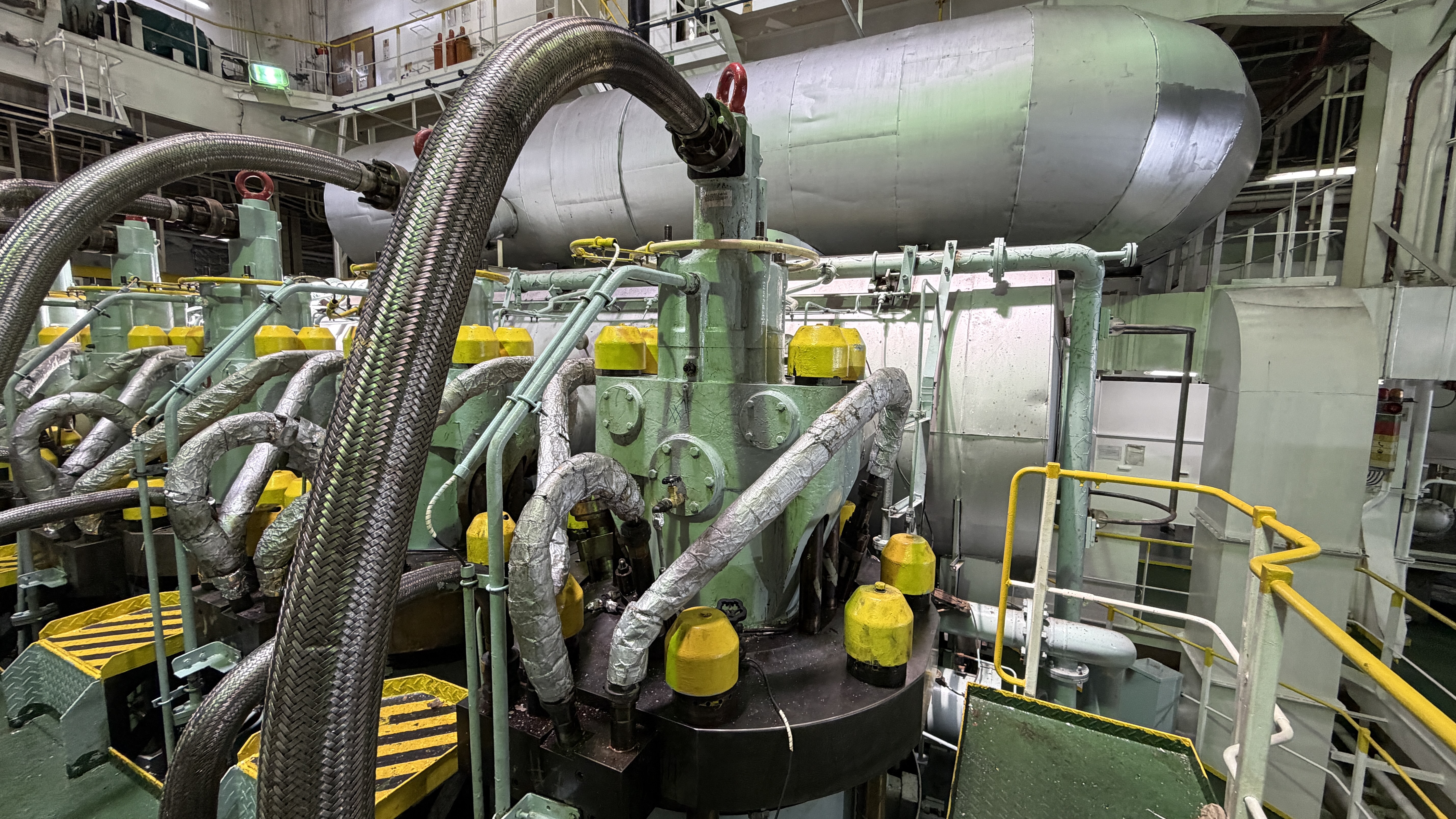
A MAN B&W ME-C engine is an electronically controlled low-speed two-stroke engine. It uses an Engine Control System to calculate and command key engine functions, while hydraulic components provide the force needed to execute those commands. The names and exact arrangement can vary between ME-C generations and control-system revisions, but common concepts include the ECS, HPS, HCU, cylinder control units, actuator control units, feedback signals, sensors, and electronically commanded fuel injection and exhaust-valve actuation.
The Hydraulic Power Supply, or HPS, provides hydraulic or servo oil pressure for the control and actuation system. The Hydraulic Cylinder Unit, or HCU, is associated with cylinder-level hydraulic actuation and control equipment. Components often referred to in ME-C discussions include FIVA valves, ELFI, ELVA, MPC, CCU, ECU and ACU, but terminology and hardware arrangement should always be confirmed against the specific engine and control-system documentation.
In broad terms, the ME-C control system receives information from speed and crank-angle sensing, load commands, control inputs, pressure signals, actuator feedback, safety systems, and other monitoring inputs. It then calculates commands for fuel injection, exhaust-valve operation, cylinder lubrication where applicable, starting/reversing logic, and other functions. The command is only useful if the hydraulic supply, control valves, actuator movement, feedback signals, wiring, and mechanical components respond correctly.
Practical comparison table
| Area | ME-C | MC-C |
|---|---|---|
| Overall control philosophy | Electronically calculated commands executed through hydraulic and mechanical actuation | Mechanically timed operation based mainly on camshaft-driven arrangements |
| Camshaft dependence | Many key timing functions are no longer dependent on a conventional camshaft profile | Camshaft is central to fuel injection and exhaust-valve timing |
| Fuel injection | Electronic command with hydraulic actuation and feedback-dependent diagnosis | Fuel pump actuation and timing are mechanically generated |
| Fuel-injection timing | Controlled by the engine control system within maker-defined logic and limits | Determined by cam profile, pump setting, linkage condition, and timing adjustment |
| Exhaust-valve actuation | Electronically commanded hydraulic actuation, with response and feedback checks where fitted | Camshaft-driven actuation through mechanical/hydraulic arrangements |
| Exhaust-valve timing | More flexible within the control-system design | Primarily governed by mechanical cam timing |
| Hydraulic control | Hydraulic pressure stability and oil cleanliness are critical to command execution | Hydraulics may be used, but the fundamental timing is mechanically driven |
| Engine-control system | ECS, control units, communication, alarms, redundancy and feedback are central to operation | Monitoring and protection are important, but basic timing is mechanical |
| Sensors | Crank-angle, speed, pressure, feedback and actuator-related signals are essential for control | Sensors support monitoring, protection and diagnosis, while timing remains mechanical |
| Starting and reversing | Commands are processed through electronic control logic and interlocks | More directly linked to conventional pneumatic/mechanical control arrangements |
| Cylinder lubrication | May include electronically controlled lubrication depending on engine configuration | Usually more conventional or mechanically/electro-mechanically arranged depending on installation |
| Diagnostics | Alarm history, event logs, feedback, command response and hydraulic status become key evidence | Mechanical inspection, timing checks and operating symptoms carry more of the diagnosis |
| Troubleshooting approach | Combine electronic, hydraulic, fuel, combustion and mechanical checks | Focus more heavily on fuel pumps, timing, cam/roller gear, linkages and conventional combustion checks |
| Maintenance focus | HPS/HCU equipment, actuators, sensors, wiring, connectors, hydraulic oil condition and conventional engine parts | Camshaft, rollers, fuel pumps, linkages, timing gear, exhaust-valve actuation and conventional engine parts |
| Oil cleanliness sensitivity | High sensitivity in hydraulic control and actuation circuits | Important for engine reliability, but less tied to electronic hydraulic command execution |
| Timing adjustment | Handled through control-system logic and authorised procedures | More physically linked to mechanical timing and fuel pump settings |
| Operating flexibility | Greater timing and control flexibility within maker-approved limits | More limited by fixed cam profiles and mechanical arrangements |
| Component complexity | More electronic/hydraulic control components in addition to conventional engine parts | More mechanically familiar but still highly precise |
| Engineer skill requirements | Requires traditional two-stroke knowledge plus hydraulic, control-system and diagnostic competence | Requires strong mechanical timing, fuel pump, linkage and conventional two-stroke knowledge |
Fuel injection differences
On MC-C engines, fuel injection timing and delivery are produced by camshaft-driven mechanical arrangements. The cam profile, pump condition, roller guide condition, fuel linkage, timing setting, fuel valve condition and fuel quality all influence combustion. If one cylinder shows poor combustion, engineers normally investigate the fuel pump, roller guide, timing, fuel valve, compression condition and exhaust valve condition.
On ME-C engines, fuel injection is electronically commanded and hydraulically actuated. The control system determines injection timing and quantity according to its approved control logic, engine condition and operating command. The physical result still depends on fuel equipment and combustion condition, but diagnosis also includes the commanded signal, hydraulic supply condition, actuator response, sensor validity, feedback signal and any alarm or event history.
This does not mean an ME-C fuel injection problem is automatically electronic. A high exhaust temperature, black smoke or cylinder imbalance may still come from a fuel valve, compression issue, liner/ring condition, exhaust valve leakage, scavenge-air problem or fuel quality. The practical difference is that engineers must compare both the conventional mechanical evidence and the electronic/hydraulic command path.
Exhaust-valve control differences
On MC-C engines, exhaust-valve operation is mechanically timed through the camshaft-driven system, commonly using hydraulic elements to transmit or execute motion. Engineers investigate exhaust-valve problems by checking timing, actuator condition, hydraulic condition, air spring or closing arrangement where fitted, linkage or mechanical actuation condition, spindle and seat condition, guide condition, leakage, deposits and temperature trends.
On ME-C engines, exhaust-valve opening is electronically commanded and hydraulically actuated. Closing arrangements and exact details vary by engine type, but the diagnostic approach normally includes actuator response, command signal, feedback where fitted, hydraulic pressure, oil cleanliness, leakage, sticking, sensor condition, control alarms and conventional valve condition. Exhaust-valve leakage, slow response or incorrect operation can appear as high exhaust-gas temperature, low compression, poor scavenging, cylinder imbalance or timing alarms.
ME-C hydraulic system: HPS, HCU and actuation
The ME-C hydraulic system provides the working force used to turn electronic commands into physical engine actions. The Hydraulic Power Supply produces and maintains the required hydraulic or servo oil pressure. The Hydraulic Cylinder Unit and associated control/actuation components distribute and apply that hydraulic energy at the cylinder level, depending on engine generation and arrangement.
Stable pressure and clean oil are essential. Contamination can cause sticking control components, slow actuator response, internal leakage, filter problems and unreliable feedback. Leakage can reduce available pressure or create unstable operation. Pressure instability, poor pump condition, accumulator issues, restriction, contaminated oil, incorrect oil condition or faulty pressure sensing may influence more than one cylinder, while a local actuator or control valve issue may affect one cylinder unit.
The important diagnostic point is relationship. Engineers should decide whether a fault is common to the hydraulic supply, local to one HCU or cylinder unit, related to a control component such as a FIVA/ELFI/ELVA where applicable, caused by feedback/sensor error, or still rooted in conventional fuel, exhaust valve, compression or mechanical condition.
Starting, reversing and control philosophy
Both MC-C and ME-C engines require safe starting-air operation, correct interlocks, reliable control air or control logic, sound starting valves, correct fuel admission and freedom of movement. The difference is how commands are generated and verified. MC-C systems are more directly linked to conventional pneumatic and mechanical control arrangements, while ME-C systems process commands through electronic control logic and execute approved sequences through controlled hydraulic, pneumatic and mechanical systems.
On ME-C engines, starting or reversing faults may involve interlocks, control-unit signals, feedback mismatch, crank-angle information, speed signals, actuator readiness, hydraulic pressure, starting-air system condition, or conventional mechanical resistance. On MC-C engines, engineers may focus more directly on air distributor function, starting valves, control-air paths, reversing mechanism, fuel pump timing and mechanical freedom.
Cylinder lubrication differences
Cylinder lubrication arrangements vary by engine type, vessel installation and control-system generation. MC-C engines are commonly associated with more conventional cylinder lubrication arrangements, while many ME-C installations use electronically controlled lubrication strategies. Engineers should not assume every engine has the same lubricator type or control method.
For ME-C engines, lubrication diagnosis may include control signals, feed-rate settings, alarm history, lubricator response, quill condition, non-return function, scrape-down or drain oil findings, liner condition and piston ring condition. For MC-C engines, the focus may be more on feed adjustment, mechanical or electro-mechanical lubricator condition, distribution, non-return valves, pipes, quills, liner wear and drain oil evidence.
Sensors, feedback and monitoring
Sensors are important on both engine types, but their role is different. On MC-C engines, sensors support monitoring, alarms, protection and trend-based diagnosis. The underlying timing and actuation of key functions remain largely mechanical. A sensor fault may mislead the operator or trigger protection, but it does not normally replace the camshaft's physical timing function.
On ME-C engines, sensor and feedback signals are part of the control loop. Crank-angle or crankshaft-position information, engine-speed signals, pressure signals, actuator feedback, control-unit communication and other inputs may influence whether commands are accepted, modified, limited or alarmed. A poor connection, faulty sensor, invalid feedback signal or communication issue can therefore affect actual engine operation or create alarms even when the mechanical component is not the root cause.
This is why ME-C troubleshooting requires engineers to compare command, feedback and physical condition. An electronic alarm is evidence, not a final diagnosis. It should be checked against hydraulic condition, sensor wiring, connectors, actuator movement, fuel equipment, exhaust-valve condition, compression and operating trends.
ME-C Engine Control System architecture
At a general level, the ME-C Engine Control System receives operating commands, safety signals, sensor inputs and feedback data, then calculates engine function commands through control units and approved software logic. Depending on engine generation and revision, terms may include MPC, CCU, ECU, ACU or similar control-unit names. Their exact role and naming must be checked against the specific documentation.
The system normally includes redundancy and failure-handling logic so that a single fault does not necessarily create an immediate propulsion failure. However, redundancy is not a substitute for proper diagnosis. Communication faults, feedback mismatch, sensor loss, hydraulic pressure problems or actuator response faults must be understood within the specific control-system architecture.
Ultimately, every electronic command must become a physical action: hydraulic pressure must be available, the control valve must move or control flow correctly, the actuator must respond, feedback must be plausible, and the mechanical engine component must be able to operate. This command-to-action chain is the heart of ME-C troubleshooting.
Timing and operating flexibility
ME-C engines provide more control flexibility than mechanically determined MC-C engines because fuel injection and exhaust-valve timing can be managed through electronic control logic within maker-approved limits. This can support optimisation for different operating conditions, part-load operation, emissions strategy and combustion control. The actual performance effect depends on engine type, tuning, condition, fuel, operating profile and maker-approved settings, so percentage improvements should not be assumed.
MC-C engines are robust and familiar to many engineers, but their timing flexibility is more limited by cam profiles and mechanical adjustment. Timing changes are physical and procedural, not dynamically controlled in the same way. This mechanical clarity can be an advantage for inspection and fault tracing, but it limits the control flexibility available compared with ME-C technology.
Maintenance comparison
MC-C maintenance places strong emphasis on camshaft condition, chain drive and timing gear, fuel pumps, roller guides, rollers, mechanical timing arrangements, linkages, exhaust-valve actuation equipment, starting and reversing equipment, fuel valves, cylinder condition and conventional running gear. Engineers inspect wear patterns, timing condition, freedom of movement, leakage, mechanical damage, pump condition, linkage adjustment and combustion evidence.
ME-C maintenance includes many of the same combustion and running components, but adds HPS/HCU equipment, hydraulic control components, FIVA or equivalent control valves where applicable, ELFI/ELVA systems where fitted, sensors, feedback devices, control units, wiring, connectors, hydraulic oil condition, filter condition, leakage checks, actuator response and alarm/event history. Cleanliness and correct handling become especially important because hydraulic/electronic control faults can be created by contamination, poor connections or disturbed feedback components.
Common ME-C problems
Common ME-C problems should be treated as diagnostic possibilities, not automatic conclusions. Hydraulic pressure instability may be related to HPS pump condition, filters, leakage, accumulator condition, oil contamination, pressure sensor errors or demand-side leakage. Actuator-response alarms may point toward a sticking hydraulic component, local leakage, poor oil cleanliness, feedback fault, control valve issue or mechanical resistance.
FIVA, ELFI or ELVA related alarms, where applicable, can be associated with the component itself, its hydraulic supply, wiring, connector condition, feedback signal, control command, oil contamination, calibration issue or the mechanical component being actuated. Sensor faults may come from the sensor, wiring, connector, power supply, signal processing, vibration damage, moisture ingress or incorrect interpretation. ME-C engines can also suffer ordinary combustion and mechanical faults such as injector problems, exhaust-valve leakage, low compression, piston-ring issues, liner wear, bearing distress and scavenge-air problems.
Common MC-C problems
Common MC-C problems often involve mechanical timing and actuation evidence. Cam or roller wear, fuel-pump condition, pump timing, linkage looseness, sticking components, exhaust-valve actuation faults, fuel valve condition, air distributor or reversing problems, and general mechanical wear can all affect cylinder performance. Symptoms may include cylinder imbalance, abnormal exhaust temperature, black smoke, abnormal injection behaviour, slow starting, knocking or increased fuel consumption.
MC-C diagnosis should still remain broad. A symptom that appears mechanical may still be caused by poor fuel quality, injector condition, compression leakage, exhaust-valve leakage, liner/ring condition, scavenge-air restriction or measurement error. The lack of ME-C style alarms does not remove the need for systematic trend review, measurements and inspection.
Symptom, possible cause and inspection
| Symptom | Possible cause | Inspection |
|---|---|---|
| Cylinder imbalance | ME-C command/feedback issue, hydraulic actuator problem, fuel equipment fault, MC-C pump/timing issue, exhaust valve leakage, compression loss, or liner/ring condition | Compare cylinder data, alarms where applicable, indicator diagrams where available, fuel equipment, exhaust valve, compression, liner and ring condition |
| Abnormal exhaust-gas temperature | Poor combustion, injection timing or quantity issue, exhaust valve leakage, scavenge-air problem, low compression, or overload | Check trends, fuel injector, fuel pump or ME-C injection control, exhaust valve operation, air path, compression and load distribution |
| Poor combustion or black smoke | Fuel atomisation problem, timing issue, low air supply, poor compression, fuel quality, or control-command issue | Inspect fuel valves, fuel pumps or ME-C fuel control, scavenge pressure, turbocharger/air cooler, compression and exhaust data |
| Abnormal injection | ME-C hydraulic/control component fault, FIVA/ELFI issue where applicable, sensor/feedback fault, MC-C fuel pump or roller guide problem | Review alarms/event history, commanded versus actual response, hydraulic pressure, fuel pump condition, roller guides, fuel valves and timing records |
| Exhaust-valve timing or operation issue | ME-C actuator/feedback/hydraulic problem, ELVA issue where applicable, MC-C cam-driven actuation problem, sticking valve or leakage | Inspect actuator response, hydraulic condition, air spring/closing arrangement, spindle, seat, guide, timing and alarm history |
| Unstable hydraulic pressure | HPS pump issue, filter restriction, leakage, accumulator problem, contamination, sensor error or high demand | Check pressure trend, oil condition, filters, leakage, pump condition, accumulators, sensors and whether fault is common or cylinder-specific |
| Actuator-response alarm | Sticking component, contamination, leakage, feedback mismatch, control valve issue or mechanical resistance | Inspect oil cleanliness, local hydraulic block, wiring/connectors, feedback signal, actuator movement and mechanical load |
| Sensor or feedback fault | Faulty sensor, damaged cable, poor connector, moisture, vibration, power supply issue or signal processing fault | Check alarm log, connector condition, wiring continuity, sensor supply, signal plausibility and related physical condition |
| Fuel-pump problem | MC-C pump wear, plunger/barrel issue, timing setting, roller guide wear, linkage problem or fuel contamination | Inspect pump condition, timing, roller guide, linkage, fuel quality and affected cylinder performance |
| Abnormal mechanical noise | Bearing issue, piston/ring problem, crosshead or guide shoe wear, loose component, combustion knock, cam/roller problem | Localise noise, review trends, inspect bearings, crosshead, guide shoes, cam/roller gear, piston assembly and combustion data |
| Increased fuel consumption | Poor timing, poor combustion, fouled air path, injector condition, cylinder imbalance, control tuning issue or mechanical wear | Compare performance data, load, fuel quality, injection condition, exhaust temperatures, scavenge pressure and engine condition |
| Repeated control alarm | ME-C control-unit issue, feedback fault, hydraulic pressure problem, wiring/connectors, actuator response or sensor plausibility | Review event sequence, affected cylinder or common system, control-unit status, hydraulic pressure, connectors and component response |
How troubleshooting philosophy differs
For an ME-C cylinder-performance problem, engineers may begin with the control-system alarm list and event history, then compare command and feedback signals, hydraulic pressure, HPS and HCU condition, FIVA or other relevant actuator/control components, sensor plausibility, wiring and connector condition, fuel equipment, exhaust-valve operation, compression and mechanical condition. The aim is to decide whether the fault is electronic, hydraulic, fuel-related, combustion-related or mechanical.
For an MC-C cylinder-performance problem, engineers may focus more heavily on fuel-pump condition, mechanical timing, cam and roller-guide condition, linkage movement, injector condition, exhaust-valve actuation and timing, compression, scavenge condition and mechanical component wear. The diagnostic evidence is often more physical, but it still needs to be compared with operating trends and measurements.
Both approaches must remain systematic. Electronic alarms do not automatically mean an electronic component has failed. Mechanical symptoms do not automatically mean a mechanical component is the only cause. Fuel, air, compression, exhaust valve condition, hydraulic condition, control logic and sensor evidence may interact.
Overhaul and inspection differences
Many overhaul activities remain broadly similar between ME-C and MC-C engines. Piston overhaul, piston-ring inspection, cylinder liner inspection, cylinder cover inspection, exhaust valve overhaul, bearing inspection, crankshaft checks, scavenge-space inspection and combustion-space cleaning still require traditional two-stroke engine practice.
The differences appear around the control and actuation systems. MC-C overhaul work may include closer attention to camshaft components, fuel pump timing, roller guides, mechanical linkages and cam-driven exhaust-valve actuation. ME-C overhaul work may include hydraulic control blocks, HPS/HCU components, actuator condition, feedback devices, control valves, sensors, wiring, connectors, software-supported diagnostics and hydraulic oil cleanliness. Disturbing an ME-C control component without cleanliness and documentation can create new faults.
Advantages and limitations
ME-C engines offer greater control flexibility, stronger diagnostic capability and optimisation potential through electronic control. They allow timing and control functions to be managed through approved control logic rather than fixed mechanical profiles alone. The limitation is increased reliance on hydraulic and electronic control systems, specialist diagnostic knowledge, oil cleanliness, sensors, feedback and authorised procedures.
MC-C engines are mechanically familiar, robust and understandable to engineers trained on conventional two-stroke machinery. Their systems are often easier to trace physically, and many faults can be inspected through mechanical condition, timing and component checks. Their limitation is that timing flexibility is more restricted by mechanical cam profiles and physical adjustment.
Neither engine type is universally better in every maintenance situation. A well-maintained MC-C engine can be reliable and straightforward to diagnose. A well-maintained ME-C engine can provide advanced control and useful diagnostic information. Poor maintenance, contamination, incorrect adjustment or incomplete troubleshooting can cause problems on either design.
What engineers moving from MC-C to ME-C need to know
Engineers familiar with MC-C engines can carry across much of their two-stroke mechanical knowledge, but ME-C troubleshooting requires a stronger link between alarms, hydraulic pressure, sensor evidence and physical component condition.
| Area | MC-C habit | ME-C approach |
|---|---|---|
| First troubleshooting step | Inspect likely mechanical causes such as pump timing, roller guides, linkage movement, fuel valves, exhaust valves and compression. | Read alarm history and event sequence first, then compare command, feedback, hydraulic pressure and the actual physical response. |
| Fuel injection checks | Focus on cam-driven pump condition, timing, plunger/barrel condition, roller gear, linkage and fuel valve condition. | Check fuel command, actuator/control component response, hydraulic supply, feedback where fitted, wiring/connectors and conventional fuel-valve condition. |
| Exhaust-valve checks | Inspect cam-driven actuation, timing, air spring/closing system, spindle, seat, guide and leakage condition. | Check electronic command, hydraulic actuation, actuator response, feedback where fitted, hydraulic oil condition, leakage and the same mechanical valve condition. |
| Hydraulic system awareness | Hydraulic checks are usually limited to conventional support systems and local leakage issues. | Understand the HPS supply path, HCU arrangement, control blocks, accumulators, filters, pressure stability and local actuator logic. |
| Oil cleanliness | Mainly treated as a lubrication and wear-control issue. | Treat oil cleanliness as a control-system reliability issue because contamination can affect hydraulic response and control components. |
| Sensor and wiring checks | Less central to the main timing and actuation logic. | Check sensor plausibility, cable condition, connectors, moisture, vibration damage and power supply before condemning major components. |
| Use of tools | Mechanical inspection, timing records, indicator diagrams and conventional measurements often lead the diagnosis. | Use maker diagnostic tools, alarm records, trend data and authorised procedures together with conventional mechanical measurements. |
| Mechanical fundamentals | Mechanical condition is the core diagnostic evidence. | Mechanical condition still matters: fuel valves, compression, exhaust valves, liners, piston rings, bearings and scavenge condition must not be ignored. |
| Documentation | Record timing, measurements, wear findings, replaced parts and running checks. | Record alarms, commanded versus actual response, hydraulic findings, sensor checks, software-supported diagnostics and mechanical evidence together. |
Measurements and acceptance limits
Condition assessment should be based on recorded measurements, visual findings, operating symptoms, and the applicable maker documentation. Acceptable limits should be confirmed against the applicable manufacturer's manual and engine-specific technical documentation.
FAQ
What is the main difference between ME-C and MC-C engines?
The main difference is control philosophy. MC-C engines use camshaft-driven mechanical timing for key cylinder functions, while ME-C engines use electronic control with hydraulic actuation for many of those functions.
Does an ME-C engine have a conventional camshaft for fuel injection and exhaust-valve timing?
ME-C engines do not rely on a conventional camshaft in the same way MC-C engines do for fuel injection and exhaust-valve timing. Exact mechanical arrangements vary by engine version, so the engine-specific manual should be checked.
What is the HPS on an ME-C engine?
The HPS, or Hydraulic Power Supply, provides hydraulic or servo oil pressure for electronically commanded engine functions. Correct pressure stability and oil cleanliness are important for reliable actuator response.
What does the HCU do?
The HCU, or Hydraulic Cylinder Unit, is associated with cylinder-level hydraulic control and actuation. Its exact arrangement and component names vary by ME-C generation and control-system revision.
What is a FIVA valve?
A FIVA valve is a fuel injection and exhaust valve actuation control component used on certain ME-C arrangements. Faults may involve the valve itself, hydraulic supply, contamination, leakage, feedback, wiring or the component being actuated.
What are ELFI and ELVA?
ELFI and ELVA are terms associated with electronic fuel injection and exhaust valve actuation arrangements on certain MAN B&W electronically controlled engines. Terminology and hardware vary, so the exact engine documentation should be used.
Are ME-C engines harder to maintain than MC-C engines?
ME-C engines are not simply harder, but they require a wider diagnostic skill set. Engineers need traditional two-stroke mechanical knowledge plus hydraulic, electronic, sensor, feedback and control-system understanding.
Can an engineer experienced with MC-C engines work on ME-C engines?
Yes, MC-C experience is valuable because the combustion and running components remain familiar. However, engineers moving to ME-C engines must learn the control system, hydraulic actuation, alarm interpretation, feedback checks and authorised diagnostic procedures.
How does troubleshooting differ?
MC-C troubleshooting focuses more on mechanical timing, fuel pumps, cam/roller gear, linkages and conventional component condition. ME-C troubleshooting adds alarm history, command versus feedback, hydraulic pressure, HPS/HCU condition, sensors, wiring and actuator response.
What happens when an ME-C sensor fails?
The result depends on the sensor, control-system design, redundancy and failure-handling logic. A sensor fault may create an alarm, limit a function, trigger backup logic or affect operation. The engine-specific control-system manual must be followed.
Which components are still mechanically overhauled on an ME-C engine?
Pistons, piston rings, cylinder liners, cylinder covers, exhaust valves, bearings, crankshaft areas, scavenge spaces, fuel valves and many running components still require conventional mechanical inspection and overhaul.
Need technical assistance?
If inspection, overhaul, troubleshooting, workshop repair, or onboard attendance is required, Dieselmech Group can review the symptoms, engine details, operating history, and available measurements before recommending the next practical step. Contact us at +65 6334 1855, email sales@dieselmech.com.sg, or submit an enquiry through the Contact Us page.
Technical note
This article is for general technical information. Actual procedures, limits, clearances, pressures, temperatures, torque values, and renewal criteria depend on the engine model, configuration, maker revision, service bulletin, vessel procedures, and class requirements. Manufacturer manuals and vessel safety procedures take precedence. Safety-critical work should be carried out by appropriately qualified personnel.
Published by Dieselmech Group Technical Team. For advice on a specific engine or fault, contact our marine engineers.