
-DQG-c1Ek.png)
Technical Article
Understanding the Hydraulic Power Supply System on MAN B&W ME-C Engines
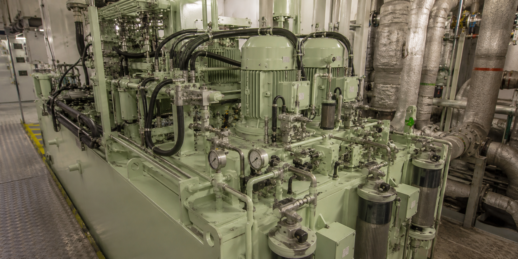
The Hydraulic Power Supply, often referred to as HPS, provides the pressurised hydraulic or servo oil energy required for electronically commanded ME-C functions such as fuel injection and exhaust-valve actuation. The Engine Control System decides what should happen and when; the HPS supplies the hydraulic energy that lets downstream HCU, FIVA or ELFI/ELVA equipment physically perform the commanded action.
What is the Hydraulic Power Supply system?
The Hydraulic Power Supply is a critical part of MAN B&W ME-C electronically controlled low-speed two-stroke engine architecture. It supplies the pressurised hydraulic or servo oil used by downstream control and actuation equipment to perform physical work.
The distinction between electronic command energy and hydraulic actuation energy is important. The Engine Control System calculates timing, quantity and sequence. The HPS does not decide injection timing or exhaust-valve timing; it provides the pressurised working medium used by the relevant control valves and actuators.
HPS architecture varies between ME-C generations, bore sizes, Mark versions and control-system revisions. Pump quantity, drive arrangement, pressure-control components, accumulators, filters, valves, sensors and downstream actuation architecture may differ. A simplified description should never be treated as one universal ME-C arrangement.
In practical terms, the HPS sits in the chain: electronic command -> control valve -> hydraulic energy -> actuator movement -> fuel injection or exhaust-valve action.
Role of the HPS within ME-C architecture
The HPS interacts with the Engine Control System, pressure sensors, Hydraulic Cylinder Units, FIVA or ELFI/ELVA arrangements where applicable, fuel injection equipment and exhaust-valve actuators. It is the common hydraulic energy source for functions that are electronically commanded but hydraulically executed.
If HPS pressure, oil condition or pressure stability is poor, downstream control components may respond slowly, inconsistently or not at all. However, poor combustion or cylinder imbalance can also come from injectors, exhaust valves, compression, fuel quality or mechanical condition, so HPS evidence must be interpreted with the whole engine.
HPS system architecture and oil-flow overview
A conceptual hydraulic path can be described as oil source or sump arrangement -> suction side -> HPS pump or pumps -> pressure-control or regulating elements -> filters -> accumulators or manifold where fitted -> distribution to HCU/control components -> actuators -> return or drain path.
Actual oil source, filtration order, accumulator arrangement, pressure-control design and return path depend on the installed engine and HPS generation. Engineers should use this flow only as a mental model before checking the maker diagram for the vessel's engine.
HPS pumps
HPS pumps provide the flow and pressure needed for the hydraulic control and actuation system. Depending on configuration, pumps may be engine-driven, electrically driven or arranged with standby/redundant capacity. Pump loading, unloading or pressure-control principles also vary by design.
Common inspection areas include abnormal noise, vibration, overheating, external leakage, suspected internal leakage, pump drive condition, suction condition, pressure response, filter condition and performance trends. Pump specifications, capacities and acceptance criteria must come from the engine-specific documentation.
Pump redundancy and standby philosophy
Critical propulsion hydraulic supplies may use multiple pumps or standby arrangements so the system can maintain required operation if one source becomes unavailable. Exact automatic changeover logic, permissives and alarm behaviour are not universal.
Engineers should review the actual control documentation before assuming how many pumps should run, when a standby pump should start or how the system behaves after a pump fault.
Servo or hydraulic oil as the working medium
The hydraulic oil transmits power, lubricates fine-clearance components, removes heat and supports reliable control-valve operation. Cleanliness, correct oil condition, absence of water contamination and control of degradation are essential for reliable ME-C hydraulic response.
Small clearances in hydraulic control equipment mean contamination can cause effects that are not immediately visible: sticking, abrasive wear, internal leakage, slow actuator response, unstable pressure and repeated hydraulic alarms.
Oil cleanliness and contamination
Contamination sources can include maintenance ingress, wear debris, degraded seals, dirty filling practices, filter bypass or failure, water ingress and debris released after component damage. Symptoms should be confirmed through inspection, filter findings and oil analysis rather than assumed from alarms alone.
When contamination is suspected, engineers should consider both upstream HPS components and downstream HCU/FIVA/ELFI/ELVA equipment that may have been exposed to the same oil.
Oil analysis and condition monitoring
Oil analysis can help trend cleanliness, water content and other maker-recommended oil-condition indicators. Filter debris, pressure trends and component history should be reviewed together.
This article does not provide universal ISO cleanliness codes, water limits or temperature limits. Targets must come from the applicable MAN B&W/Everllence instruction book, HPS documentation and vessel oil-management procedures.
Filtration system
HPS filtration may include pressure filters, return filters or other filtration stages where fitted. Differential-pressure monitoring and bypass arrangements may be present depending on design. A restricted or contaminated filter can influence pressure response and actuator reliability.
Filter changes should not end with element renewal only. Engineers should inspect debris, compare differential-pressure trends, review oil analysis and consider whether unusual contamination indicates developing pump, seal or component wear.
Filter debris interpretation
Metallic particles, seal fragments, dark degraded material or unusual contamination can indicate developing component wear or oil degradation. Debris should be considered with oil-analysis results, alarm history, pressure behaviour and recent maintenance.
Accumulator operating principle
Hydraulic accumulators, where fitted, store pressurised energy, damp pressure fluctuations and support rapid transient hydraulic demand. The gas pre-charge conceptually provides compressible energy storage behind the hydraulic system.
Incorrect pre-charge, loss of gas charge or damaged accumulator function can reduce damping and energy-storage performance, possibly contributing to pressure pulsation or unstable actuator response. Gas type, pre-charge pressure and testing values must come from maker documentation.
Accumulator inspection and safety
Accumulators contain stored hydraulic and pneumatic energy. Isolation, depressurisation, pre-charge checks, charging and dismantling are safety-critical and must be performed by qualified personnel using maker-approved procedures.
This article intentionally avoids step-by-step accumulator charging or dismantling instructions.
Pressure regulation and control
HPS pressure is maintained through pump control, regulating valves, unloading/control elements or other engine-specific arrangements. Low pressure, excessive pressure, unstable pressure and pressure pulsation can arise from different causes.
Low pressure may suggest pump, suction, leakage, filter, regulation or sensor issues. Unstable pressure may involve accumulator condition, control instability, variable leakage, demand changes or signal problems. Excessive pressure, where applicable, should be treated as a control or regulation concern requiring maker-guided investigation.
Manifold and distribution system
The manifold and distribution system may include pressure blocks, piping, flexible connections, fittings, seals, valves and supply paths to cylinder-specific hydraulic equipment. External leakage, loose or damaged connections, heat, vibration marks and abnormal return or drain behaviour should be recorded.
Internal leakage is harder to see and may appear as inability to maintain pressure, excessive pump loading, heat generation or abnormal drain/return trends.
Pressure sensors and instrumentation
Accurate pressure feedback supports alarm generation, control monitoring and diagnosis. Engineers should distinguish between a true hydraulic-pressure problem and an instrumentation problem by comparing redundant signals, local and remote readings where available, alarm chronology and physical evidence.
A low-pressure alarm can come from real pump, leakage, filter or control problems, but it can also come from sensor, wiring, connector or signal faults.
HPS pressure behaviour during operation
Hydraulic demand changes with engine speed, load and cylinder actuation. Stable supply pressure is important for repeatable response of downstream control and actuation equipment. Proprietary pressure curves, setpoints and alarm values are intentionally not stated here.
Relationship between HPS pressure and fuel injection
Downstream fuel-injection control and actuation equipment relies on adequate hydraulic energy. Insufficient or unstable HPS pressure can influence injection execution or response. At the same time, combustion symptoms can also originate from injector condition, fuel quality, compression, air supply or mechanical condition unrelated to HPS.
Relationship between HPS pressure and exhaust-valve actuation
Adequate hydraulic supply supports commanded exhaust-valve actuator operation. Exhaust-valve timing or response issues should be assessed with HPS pressure, downstream control components, air spring where fitted, actuator condition and mechanical valve condition together.
Relationship between HPS, HCU, FIVA, ELFI and ELVA
The HPS is the common hydraulic energy source. The HCU is cylinder-specific hydraulic/control equipment where fitted. FIVA or separate ELFI/ELVA components meter or direct hydraulic action for fuel injection and exhaust-valve functions depending on engine generation.
Repeated downstream component faults can sometimes be symptoms of an upstream HPS, oil-quality or contamination problem.
Common HPS failure modes
Common HPS failure modes include pump wear or performance loss, suction problems, external leakage, internal leakage, filter restriction, contamination, water ingress, accumulator charge problems, pressure-regulating/control-valve faults, sensor or instrumentation faults, wiring/connector issues, overheating, cavitation-like symptoms where technically appropriate, pressure pulsation and downstream hydraulic leakage.
Each failure mode requires evidence. Abnormal pump noise should lead to suction, drive, wear and pressure checks, not instant pump condemnation. Low pressure should lead to trend review, leakage inspection, filtration review, sensor verification and pump assessment.
Common HPS inspection points
- Hydraulic oil cleanliness, water contamination, and filter condition
- Pump condition, abnormal noise, vibration, or overheating
- Accumulator pre-charge and pressure stability where applicable
- External leakage at pipes, blocks, valves, and connections
- Pressure sensor feedback and alarm history
- Accumulator behaviour and pressure pulsation where applicable
- Manifold, pipework, flexible connections and drain/return condition
- Alarm chronology and comparison across cylinders
Symptom, possible cause and inspection
| Symptom | Possible cause | Inspection |
|---|---|---|
| Low hydraulic pressure | Pump performance loss, suction restriction, leakage, filter restriction, control valve issue or sensor error | Trend pressure, inspect filters, verify readings, check leakage and assess pump operation |
| Unstable or fluctuating pressure | Pump control hunting, accumulator issue, intermittent restriction, leakage variation, air/gas issue or sensor signal problem | Review pressure trend, demand changes, accumulator behaviour, leakage and instrumentation |
| Slow pressure build-up | Pump not loaded/running correctly, suction issue, leakage, filter restriction or control issue | Check pump status, suction condition, filters, leakage and alarm chronology |
| Repeated low-pressure alarm | Actual pressure drop or sensor/wiring issue | Compare local/remote readings, redundant sensors where fitted and first alarm sequence |
| High-pressure alarm where applicable | Pressure regulation/control issue, sensor fault or blocked path | Follow maker diagnostics and verify actual pressure before component replacement |
| Pressure pulsation | Accumulator issue, pump pulsation, control instability or demand fluctuation | Check accumulator condition where fitted, pump behaviour and pressure trend |
| One cylinder poor actuator response | Cylinder-specific HCU/FIVA/ELFI/ELVA issue or mechanical restriction | Compare other cylinders, HPS pressure and affected cylinder feedback |
| Multiple cylinders timing/actuation issues | Common HPS supply, oil condition, pressure control or instrumentation issue | Check HPS pressure, filters, oil analysis, alarms and common supply condition |
| Repeated FIVA/ELFI/ELVA alarms | Downstream component issue or common contamination/HPS instability | Check oil cleanliness, pressure stability, affected units and component history |
| Abnormal pump noise | Suction issue, aeration where applicable, wear, drive issue, restriction or internal damage | Inspect suction/drive condition, pressure trend, temperature and vibration |
| Pump overheating | Excessive internal leakage, sustained high load, restriction, cooling issue or oil problem | Check oil temperature, leakage, filters, pump loading and cooling condition where relevant |
| Excessive leakage | Seal failure, loose connection, cracked pipe, internal leakage or worn component | Distinguish external visible leakage from internal leakage indicators |
| Rapid pressure decay where accumulators are fitted | Accumulator charge issue, leakage or control valve leakage | Use maker-approved accumulator and leakage checks |
| High filter differential pressure | Restricted or contaminated filter | Inspect element, debris type, oil condition and contamination source |
| Recurring filter contamination | Wear debris, dirty maintenance, degraded seals or oil degradation | Review debris, oil analysis, recent maintenance and exposed components |
| Water detected in oil | Water ingress, cooler/seal issue or contamination during maintenance | Follow oil analysis and maker-guided contamination response |
| Abnormal oil temperature | Internal leakage, pump inefficiency, restriction, cooling issue or oil degradation | Check temperature trend, pump load, filters, leakage and cooling |
| Pressure sensor disagreement | Sensor, wiring, calibration issue or actual local pressure difference | Compare signals, connectors, local readings and alarm chronology |
| Local/remote pressure disagreement | Instrumentation fault or measurement point difference | Verify readings with approved method and check wiring/sensors |
| Unstable engine operation | HPS instability, actuator response issue, fuel problem or cylinder imbalance | Compare hydraulic pressure, alarms, cylinder trends and mechanical evidence |
| Starting difficulty | Hydraulic supply issue, interlock, timing reference, starting air or fuel admission issue | Review start sequence, HPS pressure, alarms and maker diagnostics |
Single-cylinder fault versus common HPS fault
If only one cylinder is affected while HPS pressure and other cylinders remain normal, engineers should usually give strong attention to cylinder-specific HCU, FIVA, ELFI/ELVA, fuel equipment, exhaust-valve equipment and mechanical condition.
If multiple cylinders develop similar hydraulic-response symptoms at the same time, a common HPS supply, pressure-control, oil-quality or instrumentation issue may deserve greater attention. This is diagnostic reasoning, not a hard rule.
HPS troubleshooting workflow
- Confirm the reported symptom and operating condition.
- Review alarm and event chronology, especially the first relevant alarm.
- Verify pressure readings and instrumentation plausibility.
- Trend hydraulic pressure during the affected operating condition.
- Inspect oil level/source arrangement and oil condition where applicable.
- Inspect filter differential pressure and filter element condition.
- Check for external leakage and signs of internal leakage.
- Assess pump operation, noise, vibration, temperature and drive/status.
- Consider accumulator and pressure-control condition where applicable.
- Compare behaviour across cylinders to separate common supply from cylinder-specific faults.
- Inspect downstream HCU, FIVA, ELFI or ELVA equipment where applicable.
- Check electrical and sensor feedback before replacing hydraulic components.
- Compare findings with maker documentation and avoid bypassing pressure protections.
Low hydraulic pressure troubleshooting
Potential causes include pump performance loss, pump not running or not loaded correctly, suction restriction, insufficient oil supply where applicable, external or internal leakage, filter restriction, pressure-control/regulating issue, accumulator-related effects or sensor error.
Differentiation depends on trends, local verification, leakage inspection, filter evidence, pump behaviour, oil condition and whether the symptom affects one cylinder or the common system.
Unstable or fluctuating pressure
Fluctuating pressure may involve pump control hunting, accumulator issues, intermittent restriction, control-valve instability, air/gas effects where applicable, leakage variation, changing demand or sensor signal problems. Engineers should match pressure movement to engine demand and alarm timing.
Frequent hydraulic alarms
Frequent alarms should be analysed by chronology. Compare the actual pressure trend with alarm timing and verify instrumentation before changing components. Consequential alarms from downstream cylinders may be caused by one common upstream HPS condition.
Pump abnormal noise or vibration
Abnormal pump noise or vibration may be associated with suction problems, aeration where applicable, mechanical wear, drive issues, restriction or internal damage. Sound alone should not be used as proof of pump failure; it should trigger structured inspection.
Hydraulic leakage assessment
External leakage is physically visible around pipes, blocks, seals, fittings or components. Internal leakage may show as inability to maintain pressure, higher pump loading, heat generation or abnormal return/drain behaviour.
Leak tracing must follow maker procedures and vessel safety precautions because the system may contain high pressure and stored energy.
System overheating
HPS overheating may result from excessive internal leakage, pump inefficiency, restriction, sustained high load, cooling issues where relevant or degraded oil condition. Temperature symptoms should be linked with pump load, pressure stability, filters, leakage and oil analysis.
HPS component, function, common problems and inspection focus
| Component | Function | Common Problems | Inspection Focus |
|---|---|---|---|
| Pump(s) | Generate hydraulic flow and pressure | Wear, overheating, noise, leakage, poor response | Noise, vibration, temperature, pressure build-up, drive/status and trends |
| Suction arrangement | Supplies oil to pump inlet where applicable | Restriction, aeration, low supply, contamination | Oil source, suction condition, restrictions and maintenance history |
| Pressure filters | Remove particles from supply oil | Restriction, bypass, recurring debris | Differential pressure, debris type, element condition and source investigation |
| Accumulators | Store energy and damp fluctuations where fitted | Loss of charge, poor damping, leakage | Pressure pulsation, decay behaviour and maker-approved checks |
| Pressure-control/regulating valves | Maintain required pressure behaviour | Sticking, wear, instability, wrong response | Pressure trend, oil cleanliness and maker diagnostics |
| Manifold/distribution piping | Distributes pressure to downstream controls | Leakage, vibration damage, loose fittings | External leakage, heat/vibration marks and connection integrity |
| Pressure sensors | Provide pressure feedback and alarms | Signal error, wiring fault, disagreement | Sensor agreement, connectors, local/remote readings and chronology |
| Oil source/reservoir arrangement | Provides working oil where applicable | Low level, contamination, water ingress | Oil condition, sampling history and source integrity |
| Downstream supply to HCU/control valves | Feeds cylinder actuation equipment | Restriction, leakage, contamination exposure | Affected cylinders, command/feedback and downstream alarms |
| Return/drain paths | Return or drain hydraulic oil | Restriction, abnormal flow, leakage evidence | Drain trends, heat and maker-guided inspection |
Key HPS condition indicators
| Parameter/Observation | Why It Matters | What Abnormal Behaviour May Suggest | Related Checks |
|---|---|---|---|
| Hydraulic pressure | Actuation requires adequate pressure | Pump, leakage, filter, control or sensor issue | Pressure trend, local readings, filters and leakage |
| Pressure stability | Repeatable actuator response depends on stable supply | Accumulator, pump control, leakage or demand issue | Trend data, accumulators, pump and downstream demand |
| Pump status | Confirms hydraulic source availability | Pump not running/loaded or standby issue | Control status, drive and alarm history |
| Pump temperature/noise | Indicates load and mechanical condition | Wear, suction problem, restriction or internal leakage | Temperature trend, vibration and pressure response |
| Filter differential pressure | Shows restriction/contamination | Blocked filter or debris generation | Element inspection and oil analysis |
| Oil cleanliness | Protects precision components | Contamination or maintenance ingress | Oil sampling, filters and component history |
| Water contamination | Can affect oil and components | Ingress or handling issue | Oil analysis and source investigation |
| Oil temperature | Affects viscosity and component reliability | Overheating, leakage, restriction or cooling issue | Pump load, leakage and cooling where relevant |
| Accumulator behaviour | Supports damping and transient demand | Charge or leakage issue | Pressure pulsation and approved accumulator checks |
| External leakage | Loss of oil and pressure integrity | Seal, fitting or pipe issue | Visual inspection and safe leak tracing |
| Alarm/event history | Shows sequence and recurrence | Root cause may be earlier than final alarm | Chronology and related system data |
| Sensor agreement | Separates process from instrumentation fault | Sensor/wiring fault or local pressure difference | Compare signals and local readings |
| Downstream actuator response | Shows whether hydraulic energy produces action | HPS issue, control valve issue or mechanical restriction | Command/feedback and cylinder comparison |
Measurements and acceptance limits
HPS condition assessment may include maker-specified operating pressure, pressure stability, filter differential pressure, accumulator pre-charge where applicable, pump performance indicators, oil condition, oil temperature, leakage, sensor calibration or verification and component-specific measurements.
Every numerical target must be taken from the engine-specific maker manual, control-system documentation, HPS component documentation, service letters/bulletins, vessel procedures and class requirements.
Planned HPS inspection and maintenance
Planned inspection should include routine visual checks, leak checks, pressure trending, filter monitoring or change according to maker criteria, oil-condition monitoring, pump observation, sensor verification, accumulator checks where required, hose/pipe/manifold inspection and alarm-history review.
Maintenance intervals are not universal and must be taken from the applicable documentation.
Maintenance after a contamination event
After contamination, engineers should identify the source, inspect affected filters, consider oil analysis, assess whether downstream components were exposed and follow maker-approved cleaning or flushing procedures where required. A generic flushing recipe is unsafe because hydraulic layouts differ.
Maintenance after pump replacement or HPS repair
After repair, verify correct component configuration, cleanliness, connection integrity, leakage condition, pressure response, alarm status and downstream actuator behaviour according to maker procedures. Do not use generic commissioning pressures or sequences.
Post-maintenance testing and verification
Post-maintenance verification should include controlled system restoration, leakage checks, pressure build-up and stability confirmation, sensor agreement, alarm status, pump behaviour and normal response of affected cylinders or control components. Controlled engine load-up should be monitored where applicable.
Root-cause investigation after repeated HPS faults
Repeated pump or control-component replacement without identifying contamination, suction problems, internal leakage, oil degradation, filtration problems, overheating or incorrect operating conditions can lead to repeat failure. HPS faults should be investigated as a system, not only as failed parts.
Before replacing an HPS pump or control component
- Review alarm history and first relevant alarm.
- Verify actual pressure trend and sensor plausibility.
- Inspect oil condition, filters and debris.
- Check suction condition where applicable.
- Check external and internal leakage indicators.
- Confirm pump drive/status and operating condition.
- Consider accumulator behaviour where fitted.
- Compare downstream demand and affected cylinders.
- Follow maker diagnostic guidance before renewal.
HPS versus HCU versus FIVA
HPS supplies common hydraulic power. HCU is cylinder-specific hydraulic/control equipment where applicable. FIVA or separate ELFI/ELVA devices control or direct hydraulic action for fuel and exhaust functions depending on engine generation.
HPS versus conventional MC-C systems
On ME-C engines, HPS condition is central because electronic commands need hydraulic power to become physical injection and exhaust-valve action. Conventional MC-C engines rely more directly on mechanically timed camshaft functions. The broader differences are covered in the ME-C vs MC-C technical article.
Future Technical Media
A useful HPS illustration would show a simplified conceptual oil-flow path: Oil Source/Suction -> HPS Pump(s) -> Pressure Regulation -> Filter(s) -> Accumulator(s) -> Pressure Manifold -> HCU/FIVA or ELFI/ELVA -> Fuel Injection/Exhaust Valve Actuation -> Return/Drain. Dashed arrows should show pressure-sensor feedback to the Engine Control System.
A second diagram titled How HPS Hydraulic Energy Becomes Cylinder Actuation should show ECS Command -> FIVA/ELFI/ELVA Control -> HPS Oil Flow -> Hydraulic Actuator -> Mechanical Movement. Both diagrams must be labelled simplified conceptual architecture because actual arrangement varies by ME-C generation and engine configuration.
FAQ
What is the HPS on a MAN B&W ME-C engine?
The HPS is the Hydraulic Power Supply that provides pressurised hydraulic or servo oil energy for electronically commanded actuation functions on applicable ME-C engines.
What does the Hydraulic Power Supply do?
It supplies hydraulic energy to downstream control and actuation equipment. It does not calculate timing; the Engine Control System does that.
Why does an ME-C engine need servo oil?
Servo or hydraulic oil transmits power from the HPS to control valves and actuators so electronic commands can create mechanical movement.
What components are included in the HPS?
Depending on configuration, the HPS may include pumps, filters, pressure-control elements, accumulators, manifolds, sensors, piping, fittings and return/drain paths.
How does the HPS interact with FIVA?
Where FIVA is fitted, HPS oil supplies the hydraulic energy that FIVA-controlled functions direct for fuel injection and exhaust-valve actuation.
What is the difference between HPS and HCU?
HPS is the common hydraulic power source. HCU is cylinder-specific hydraulic/control equipment where that arrangement is fitted.
What causes low HPS pressure?
Possible causes include pump performance loss, suction restriction, leakage, filter restriction, pressure-control issues, accumulator effects or sensor error.
What causes unstable HPS pressure?
Possible causes include pump control instability, accumulator issues, intermittent restriction, variable leakage, changing demand or sensor signal problems.
Can dirty hydraulic oil cause ME-C alarms?
Yes. Contamination can cause sticking, wear, internal leakage, slow actuator response and repeated hydraulic or control alarms.
What happens if an HPS filter becomes restricted?
A restricted filter may affect pressure response and trigger differential-pressure alarms where monitored. Debris should be inspected, not simply discarded.
What does an accumulator do in the HPS?
Where fitted, an accumulator stores hydraulic energy and helps damp pressure fluctuations or transient demand.
Can an HPS sensor fault look like low hydraulic pressure?
Yes. Sensor, wiring or connector faults can create low-pressure alarms, so engineers should verify actual pressure condition and signal plausibility.
How can engineers distinguish a common HPS fault from a single-cylinder fault?
Compare HPS pressure and other cylinders. One affected cylinder often points toward cylinder-specific equipment or mechanical condition; multiple simultaneous symptoms may point toward common HPS supply, oil quality or instrumentation.
What causes repeated HPS pump problems?
Repeated pump problems may involve contamination, suction issues, internal leakage, overheating, incorrect operating conditions, oil degradation or unresolved system faults.
What should be checked after replacing an HPS pump?
Check cleanliness, correct configuration, leakage, pressure build-up, pressure stability, sensor agreement, alarm status, pump behaviour and downstream actuator response according to maker procedure.
How important is oil cleanliness on ME-C engines?
It is critical because fine-clearance hydraulic control equipment is sensitive to particles, water and degraded oil.
Technical glossary
| Term | Meaning |
|---|---|
| HPS | Hydraulic Power Supply; common source of hydraulic/servo oil pressure for ME-C actuation functions. |
| Servo oil / hydraulic oil | Working medium that transmits hydraulic power and lubricates fine-clearance control components. |
| HCU | Hydraulic Cylinder Unit; cylinder-specific hydraulic/control equipment where fitted. |
| FIVA | Fuel Injection and Valve Actuation arrangement where applicable. |
| ELFI | Electronic Fuel Injection arrangement where applicable. |
| ELVA | Electronic Exhaust Valve Actuation arrangement where applicable. |
| Accumulator | Device that stores pressurised hydraulic energy and damps pressure fluctuations where fitted. |
| Differential pressure | Pressure difference across a filter or component, often used to indicate restriction. |
| Internal leakage | Leakage within a component or circuit that is not externally visible but can affect pressure and heat. |
| Pressure feedback | Sensor signal reporting hydraulic pressure to monitoring/control systems. |
| Pressure stability | Ability of the HPS to maintain steady usable pressure during changing hydraulic demand. |
Measurements and acceptance limits
Condition assessment should be based on recorded measurements, visual findings, operating symptoms, and the applicable maker documentation. Acceptable limits should be confirmed against the applicable manufacturer's manual and engine-specific technical documentation.
Need technical assistance?
If inspection, overhaul, troubleshooting, workshop repair, or onboard attendance is required, Dieselmech Group can review the symptoms, engine details, operating history, and available measurements before recommending the next practical step. Contact us at +65 6334 1855, email sales@dieselmech.com.sg, or submit an enquiry through the Contact Us page.
Technical note
This article is for general technical information. Actual procedures, limits, clearances, pressures, temperatures, torque values, and renewal criteria depend on the engine model, configuration, maker revision, service bulletin, vessel procedures, and class requirements. Manufacturer manuals and vessel safety procedures take precedence. Safety-critical work should be carried out by appropriately qualified personnel.
Published by Dieselmech Group Technical Team. For advice on a specific engine or fault, contact our marine engineers.