
-DQG-c1Ek.png)
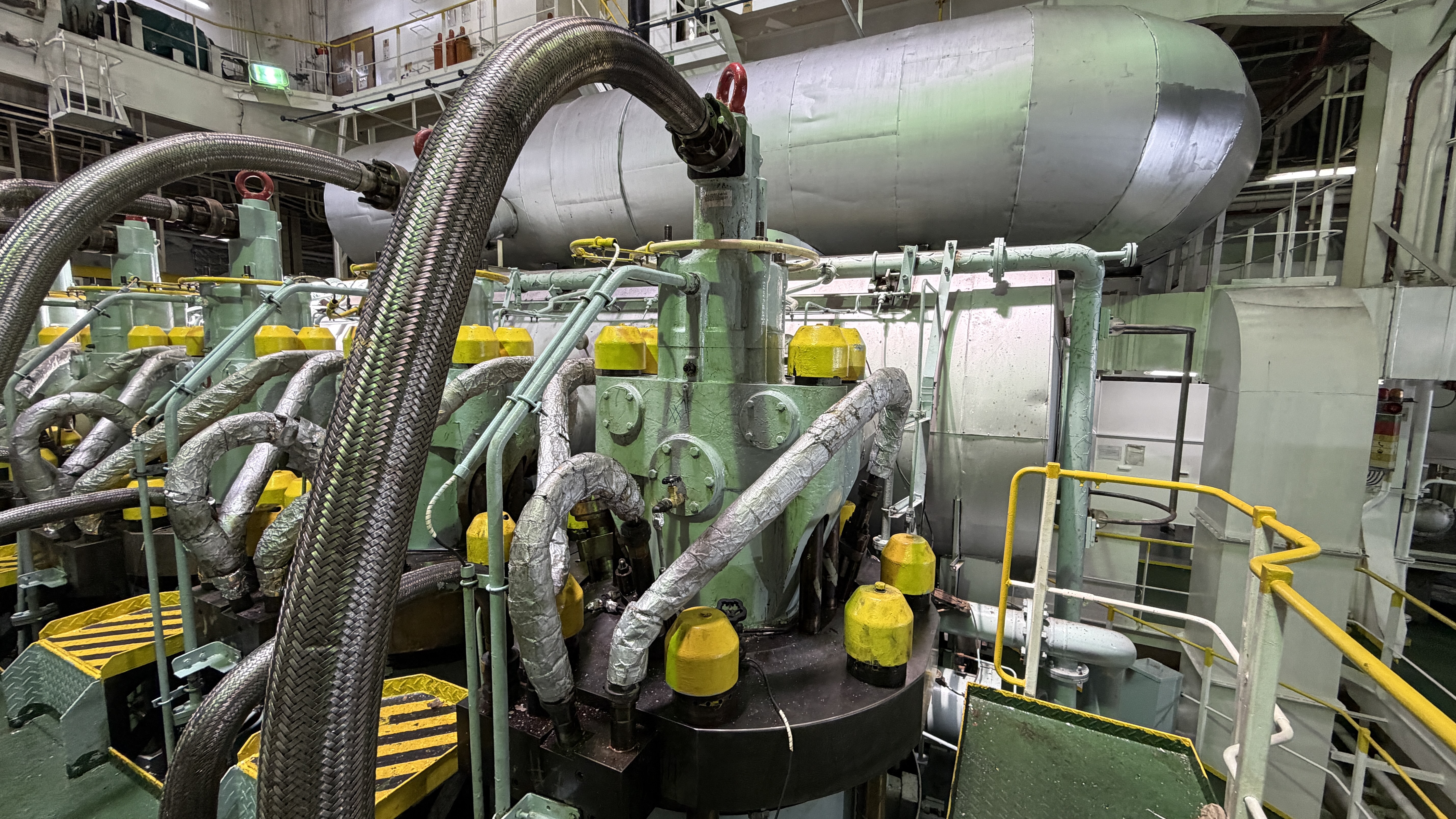
Technical Article
MAN B&W ME-C Engine: System Overview and Operating Principles
A MAN B&W ME-C engine is an electronically controlled low-speed two-stroke main engine where fuel injection, exhaust-valve operation and cylinder lubrication are calculated by an electronic control system and executed through hydraulic or electro-hydraulic actuation. Conventional mechanical running components remain fundamental, so ME-C troubleshooting must follow the complete chain from command, control logic, electrical signal and hydraulic action to mechanical movement, combustion result and feedback.
What is a MAN B&W ME-C engine?
A MAN B&W ME-C engine is an electronically controlled low-speed two-stroke marine diesel engine. The ME concept replaces the conventional mechanically timed camshaft functions used for fuel injection and exhaust-valve operation on MC and MC-C engines with electronically calculated commands executed through hydraulic or electro-hydraulic actuation.
The engine is still a large two-stroke diesel engine. The crankshaft, crosshead, connecting rod, piston, piston rings, cylinder liner, bearings, fuel injectors, exhaust-valve spindle and other mechanical components remain central to reliable operation. Electronic control does not remove the need for conventional marine engineering inspection; it adds another diagnostic layer.
ME-C architecture has evolved across engine generations, Mark versions, bore sizes and control-system revisions. Component names and arrangements can differ. Terms such as FIVA, ELFI, ELVA, HPS, HCU, MPC, ECU, CCU, ACU, MOP and Alpha Lubricator should only be applied where they match the actual engine configuration and documentation.
MAN B&W remains the established engine-family terminology used by engineers for these engines, while current maker/company naming may appear in newer documentation. This is a naming and documentation context, not a separate engine technology.
Evolution from MC-C to ME-C
Electronically controlled low-speed engines were introduced to give more flexible control of injection timing, injection characteristics, exhaust-valve timing and cylinder lubrication than a purely camshaft-timed mechanical system can provide. For engineers, the important change is that timing is calculated electronically and executed through controlled hydraulic action rather than being fixed primarily by a cam profile.
Compared with MC-C engines, ME-C engines require engineers to understand control units, sensors, feedback, hydraulic power supply, servo or hydraulic oil condition, actuator response and alarm chronology alongside conventional engine inspection. A separate Dieselmech guide covers ME-C vs MC-C Engines: Key Technical Differences in more direct comparison.
ME-C system architecture
A useful way to understand ME-C operation is to trace the information and energy path. A bridge or engine command requests speed or load. The Engine Control System receives this demand together with crank-angle reference, engine-speed signals, safety status, hydraulic pressure data, cylinder-related information and other sensor inputs. The control logic calculates cylinder-specific commands.
Those electronic commands are sent to the relevant cylinder-control and auxiliary-control hardware. Electro-hydraulic components then direct hydraulic energy from the Hydraulic Power Supply to create physical movement for fuel injection and exhaust-valve actuation. Sensors and feedback signals confirm whether the expected response occurred. The monitoring and alarm system then records status, deviations and faults.
When the engine receives a command to increase load, the control system does not simply move a mechanical fuel rack. It evaluates demand, operating condition, timing reference and limits, then adjusts cylinder fuel commands and related functions according to the approved control logic for that engine version.
Engine Control System
The Engine Control System, often shortened to ECS in documentation, coordinates command processing, engine-speed control, cylinder control, auxiliary or support functions, safety interaction, communication, monitoring, alarms and redundancy. Exact architecture and naming vary with control-system generation.
Control-unit terminology may include ECU, CCU, ACU, MPC-based hardware or other maker-specific names. In general terms, Engine Control Units process engine-level functions, Cylinder Control Units handle cylinder-specific commands and feedback, and Auxiliary Control Units manage supporting functions where applicable. These units receive input signals, execute approved control logic and issue commands to actuators. They do not directly create the mechanical force required for injection or exhaust-valve movement; hydraulic and mechanical systems do that work.
Engineers should read the actual control-system documentation for the installed engine before applying terminology. A fault on one generation may not be named or arranged the same way on another.
Main Operating Panel and diagnostic interface
The Main Operating Panel, where fitted, gives engineers access to engine status, parameter display, alarm and event history, cylinder data, trends, control status and authorised diagnostic functions. It is a diagnostic and monitoring interface as much as an operating display.
There is a clear difference between observing diagnostic information and changing protected engine parameters. This article does not provide bypass instructions, protected settings, calibration values or procedures for defeating safety logic. Any authorised adjustment must follow maker documentation, vessel procedures and access-control rules.
Sensors, command signals and feedback
ME-C control depends on reliable input and feedback. Important signals can include crankshaft position or crank-angle reference, engine speed, hydraulic or servo-oil pressure, actuator feedback, cylinder-related feedback, lubrication indication, safety status and other monitoring inputs depending on configuration.
A command signal is what the control system requests. A feedback signal is what a sensor or position device reports. The mechanical action is the physical movement or process that results. A disagreement between command and feedback can help identify whether the problem is electrical, hydraulic, mechanical, sensor-related or process-related.
A control-system alarm does not automatically mean an electronic control unit has failed. Wiring, connectors, hydraulic pressure, contamination, sticking components, mechanical leakage, fuel equipment or compression condition may all create control-related symptoms.
Crank-angle sensing and timing reference
Accurate crankshaft angular-position information is essential because fuel injection and exhaust-valve operation are electronically timed events. The control system must know where the crankshaft is before it can calculate when a cylinder event should occur.
Loss, disagreement or implausibility of timing/reference signals can affect control-system operation, alarms and permissive logic. The exact sensors, redundancy and fallback behaviour vary by control-system version, so sensor tolerances and recovery logic must be checked from the maker documentation.
Hydraulic Power Supply
The Hydraulic Power Supply, or HPS where that terminology applies, provides the hydraulic or servo-oil energy used to actuate electronically commanded engine functions. Mechanical or electrical power is converted into controlled hydraulic pressure through pumps, pressure regulation or control, accumulators where fitted, filters, piping and monitoring.
Stable pressure and clean oil are critical. Inadequate or unstable hydraulic supply may appear as pressure alarms, slow actuator response, unstable cylinder behaviour, repeated control alarms or operating instability. These symptoms are not definitive diagnoses; they indicate that hydraulic supply, sensors, leakage, filters, accumulators where fitted and actuator demand should be checked systematically.
Servo and hydraulic oil cleanliness
Fine-clearance hydraulic control components can be sensitive to contamination. Particles, degraded oil, water or debris can contribute to sticking, wear, internal leakage, unstable response and repeated control-component faults.
When repeated hydraulic-control faults occur, engineers should consider filter history, oil condition, contamination sources, maintenance records, recent component failures and cleanliness during previous work. Universal cleanliness codes should not be invented; the acceptable condition must be verified for the specific engine and hydraulic system.
Hydraulic Cylinder Unit
The Hydraulic Cylinder Unit, where that arrangement and terminology apply, links electronic cylinder commands with hydraulic actuation at the cylinder level. It converts control instructions and hydraulic energy into controlled physical action for fuel injection and exhaust-valve operation.
HCU-associated components differ by generation and configuration. Engineers should identify whether the engine uses a combined FIVA arrangement, separate ELFI/ELVA functions or another maker-specific configuration before applying troubleshooting procedures.
FIVA operating principle
On engines equipped with FIVA arrangements, the Fuel Injection and Valve Actuation function directs hydraulic energy for fuel injection and exhaust-valve actuation according to electronic commands. Conceptually, the control system requests an event, the FIVA-related control movement directs hydraulic flow, and the resulting hydraulic action causes the actuator movement required for injection or valve operation.
Typical diagnostic considerations include command and feedback disagreement, sticking, internal leakage, contamination, unstable hydraulic supply, wiring or connector issues and mechanical restriction in the actuated equipment. This article does not provide bench-adjustment procedures, protected calibration values or universal electrical/hydraulic measurements.
ELFI and ELVA arrangements
Some ME engine generations or configurations use separate Electronic Fuel Injection and Electronic Exhaust Valve Actuation functions rather than a combined FIVA arrangement. ELFI conceptually controls the fuel-injection actuation function, while ELVA conceptually controls exhaust-valve actuation.
The practical lesson is simple: identify the actual installed control-system generation before diagnosing. A symptom that engineers describe as a FIVA issue on one engine may involve separate ELFI or ELVA equipment on another.
ME-C fuel injection operating principle
Fuel injection begins with engine demand and crank-angle information. The control system calculates the required injection timing and quantity according to approved control logic, then sends a cylinder-specific command. Electro-hydraulic control action then causes the relevant hydraulic/mechanical process that generates injection through the fuel-pressure and injector system.
Electronic control allows injection characteristics to vary with operating condition more flexibly than a fixed mechanical cam profile. However, the final injection event is still physical: fuel pressure, fuel valve condition, nozzle condition and fuel-system integrity remain critical.
The control side and high-pressure fuel side should be diagnosed together but not confused. An electronic command may be correct while a fuel valve leaks or atomises poorly. Conversely, a good injector cannot correct a failed command, feedback or hydraulic actuation issue.
Fuel injector and fuel valve relationship
Conventional injector condition remains important on ME-C engines. Poor atomisation, leakage, nozzle damage, incorrect opening behaviour, deposits or fuel contamination can produce poor combustion, black smoke, high exhaust temperature or cylinder power deviation that may initially look like a control problem.
Fuel-valve inspection and testing should follow the relevant fuel injector testing procedure. ME-C troubleshooting should compare fuel equipment condition with cylinder data, alarms, command/feedback information and mechanical condition.
Exhaust-valve operating principle
Exhaust-valve operation follows a similar command-to-action chain. The control system calculates exhaust-valve timing, sends an electronic command, hydraulic control and actuation create movement, the exhaust-valve actuator opens the spindle, and the valve closes through its designed closing arrangement such as an air spring where applicable.
Electronic timing differs from MC-C camshaft-controlled timing, but the exhaust-valve spindle, seat, guide, actuator, hydraulic parts and air-spring system remain physical components that require conventional inspection and overhaul. Leakage, sticking, poor seating or actuator problems can all affect cylinder performance.
Exhaust-valve air spring
Where fitted, the exhaust-valve air spring provides closing force and helps return the exhaust valve after opening. Inspection considerations include leakage, pressure stability, sealing condition, piping, valve movement, deposits and related alarms.
Engine-specific air-spring pressures and test procedures are not provided here. They must be taken from the maker manual for the exact engine.
Electronically controlled cylinder lubrication
The Alpha Lubricator or Alpha Cylinder Lubrication system, where fitted, controls cylinder-oil delivery electronically according to operating requirements. The purpose is still conventional: maintain a protective oil film, support piston-ring and liner condition and control wear/corrosion in the cylinder.
Electronic control does not eliminate scavenge inspection, drain-oil assessment, liner inspection or piston-ring inspection. Feed rates, adjustment procedures and acceptance criteria must be taken from the applicable engine documentation.
Starting, stopping and reversing principles
At a system level, ME-C electronic control coordinates engine commands, crank-angle information, starting-air control, fuel admission and direction logic. Electronic timing removes the need for conventional mechanical camshaft reversing for controlled fuel and exhaust-valve functions.
Starting and reversing sequences are protected by safety logic and interlocks. This article explains the principle only and does not provide instructions for overriding interlocks, forcing fuel admission or bypassing safety functions.
Engine speed and load control
Requested speed or load, governor/control logic, cylinder fuel commands and operating condition interact continuously. One important characteristic of electronically controlled engines is cylinder-to-cylinder command flexibility, which can support balancing and control strategies where provided by the engine configuration.
Operating modes and optimisation strategies vary by version. Engineers should avoid assuming that a feature available on one ME-C generation applies to another.
Redundancy and failure philosophy
Propulsion engines require fault-tolerant design. Depending on configuration, redundancy may include alternative sensors, control channels, power supplies, communication paths or other duplicated arrangements. The control system detects faults, generates alarms and may maintain, limit or restrict operation according to the nature of the failure.
Fallback behaviour is version-specific. Do not assume universal emergency behaviour, available modes or restart logic without checking the exact documentation.
Control power and electrical supply
Stable electrical supply, control power, communication and connector condition are essential to ECS operation. Practical inspection areas include cabinet condition, power supply status, terminal tightness, moisture, heat, vibration, cable routing, connector condition and alarm/event history.
Invasive electronic repair, board replacement and calibration should be handled only by authorised personnel following maker procedures. Many apparent electronic failures are caused by power, wiring, connector or sensor issues.
Alarms, events and diagnostic philosophy
An alarm is a symptom, not the root cause. Effective diagnosis reviews alarm chronology, identifies the first relevant alarm, checks associated sensor values, compares command and feedback, and considers hydraulic and mechanical evidence before replacing components.
Consequential alarms can distract from the original fault. For example, a hydraulic pressure issue may generate cylinder-control alarms, actuator-response alarms and combustion symptoms. The first meaningful change in the timeline is often more useful than the loudest final alarm.
ME-C troubleshooting workflow
- Verify the reported symptom and operating condition.
- Review alarm and event history in chronological order.
- Compare cylinder performance, exhaust temperatures and trend data.
- Check relevant sensor values, feedback data and command/feedback relationship.
- Verify hydraulic supply, pressure stability, leakage, filters and oil condition.
- Inspect electrical connections, control power status, cabinets and communication alarms.
- Assess actuator or control-component response without bypassing protections.
- Inspect fuel injectors, fuel valves and high-pressure fuel equipment as applicable.
- Inspect exhaust-valve movement, air spring and conventional valve condition.
- Check compression and conventional mechanical condition such as piston, ring, liner and bearing evidence.
- Compare all findings with engine-specific maker documentation before deciding repair scope.
Cylinder power imbalance troubleshooting
Cylinder power deviation should be diagnosed with electronic, hydraulic and mechanical evidence together. Relevant data can include exhaust-temperature trends, cylinder-pressure or indicator data where available, injection-related feedback, exhaust-valve operation, injector condition, compression, piston/ring/liner condition and hydraulic/control-system alarms.
Avoid immediately blaming the electronic system. A leaking exhaust valve, poor injector, low compression or liner/ring problem can create symptoms that resemble a control problem.
Unstable engine operation
Unstable operation may involve hydraulic-pressure fluctuation, sticking or leaking control components, sensor-signal issues, fuel-system problems, cylinder imbalance, abnormal combustion or mechanical condition. The correct response is to establish which part of the command-to-combustion chain is unstable.
Repeated control alarms
Repeated control alarms should be investigated by reviewing alarm chronology, sensor plausibility, wiring and connectors, hydraulic condition, actuator feedback and the related physical equipment. Replacing a control component without checking contamination, supply pressure and mechanical freedom can lead to repeat failure.
Symptom, possible cause and inspection
| Symptom | Possible cause | Inspection |
|---|---|---|
| Cylinder power deviation | Control command issue, hydraulic response issue, injector fault, exhaust-valve leakage or compression issue | Compare alarms, feedback, exhaust temperature, cylinder pressure where available, injector condition and mechanical condition |
| High exhaust-gas temperature | Poor injection, exhaust-valve leakage, low compression, overload or timing/actuation issue | Check injector, exhaust valve, compression, command/feedback data and load history |
| Low cylinder power | Fuel command issue, poor fuel valve, compression loss, exhaust-valve fault or hydraulic actuator response | Compare cylinder data, fuel equipment, exhaust-valve movement and mechanical evidence |
| Poor combustion | Injector defect, low compression, timing issue, cylinder lubrication or air/exhaust issue | Inspect fuel valve, indicator data, liner/ring condition and control feedback |
| Black smoke | Poor atomisation, excessive fuel, air shortage, timing issue or cylinder imbalance | Check fuel injectors, scavenge/air path, cylinder data and control commands |
| Unstable engine speed | Governor/control issue, hydraulic instability, sensor signal issue, fuel issue or cylinder imbalance | Review speed/load command, alarms, hydraulic pressure and cylinder trends |
| Repeated cylinder-control alarm | Sensor, wiring, feedback, actuator, hydraulic supply or mechanical restriction | Review first alarm, command/feedback and relevant physical equipment |
| Injection-related alarm | Control signal issue, hydraulic actuation issue, fuel-system problem or feedback fault | Check alarm chronology, HPS condition, fuel valve and control component response |
| Exhaust-valve actuation alarm | ELVA/FIVA issue, actuator leakage, air spring issue, spindle sticking or feedback fault | Inspect command/feedback, hydraulic supply, actuator, air spring and valve movement |
| Hydraulic/servo-oil pressure alarm | Pump, leakage, filter, accumulator where fitted, sensor or control issue | Trend pressure, inspect filters, leakage, local readings and oil condition |
| Fluctuating hydraulic pressure | Leakage, accumulator issue, pump control issue, contamination or sensor problem | Check pressure stability, demand changes, filters and instrumentation |
| Slow actuator response | Low pressure, contamination, sticking component, internal leakage or mechanical restriction | Check hydraulic supply, oil cleanliness, actuator feedback and mechanical freedom |
| FIVA-related fault where applicable | Sticking, leakage, contamination, feedback issue, wiring or hydraulic instability | Confirm configuration, compare command/feedback and inspect hydraulic/oil condition |
| ELFI/ELVA-related fault where applicable | Separate injection or exhaust-valve control issue | Identify actual arrangement and inspect the relevant control path |
| Sensor disagreement | Faulty sensor, wiring, calibration issue, connector problem or actual process difference | Check plausibility, wiring, history and maker diagnostics |
| Crank-angle/reference fault | Timing sensor issue, wiring, reference disagreement or signal implausibility | Review timing/reference alarms and maker diagnostic procedure |
| Communication/control-unit alarm | Power, communication, cabinet, connector or hardware issue | Check power status, connections, cabinet condition and alarm chronology |
| Abnormal cylinder lubrication indication | Lubricator control issue, sensor/feedback fault, blocked delivery or operating condition | Check Alpha system status where fitted, delivery evidence and liner/ring condition |
| Starting difficulty | Starting air, interlock, timing reference, fuel admission or control status issue | Review start sequence, alarms, air system, crank-angle signal and fuel permissives |
| Failure to start | Safety interlock, no start air, no fuel command, reference fault or mechanical restriction | Follow maker start troubleshooting and do not bypass protections |
| Abnormal exhaust-valve operation | Actuation, air spring, spindle, seat, guide, feedback or hydraulic fault | Inspect valve movement, feedback, air spring and physical condition |
| Repeated component faults | Contamination, unstable supply, wiring, heat/vibration, incorrect diagnosis or unresolved mechanical cause | Check history, oil cleanliness, supply stability and root cause before renewal |
Control-system symptom, hydraulic cause and mechanical cause comparison
| Symptom | Possible control-system direction | Possible hydraulic direction | Possible mechanical/combustion direction |
|---|---|---|---|
| Cylinder power deviation | Command, sensor or feedback issue | Slow/sticking actuator or unstable pressure | Injector fault, exhaust-valve leakage, compression loss |
| High exhaust temperature | Timing/command deviation or bad feedback | Exhaust-valve actuation response issue | Burnt valve, poor injector, piston/ring/liner issue |
| Repeated actuation alarm | Wiring, control unit or feedback signal | Contamination, leakage or low pressure | Sticking spindle, actuator resistance or worn equipment |
| Unstable speed | Speed signal, governor logic or command issue | Hydraulic pressure fluctuation | Cylinder imbalance, fuel quality, mechanical defect |
| Starting failure | Interlock, control status or timing reference | Insufficient actuator or control pressure | Starting-air valve fault, compression or mechanical resistance |
ME-C maintenance focus
Maintenance should cover ECS cabinets and control equipment, sensors and feedback devices, wiring and connectors, HPS equipment, hydraulic filters and oil condition, HCU/FIVA/ELFI/ELVA equipment where applicable, cylinder lubrication equipment, fuel injectors, exhaust valves and conventional running components.
Electronically controlled engines still require all conventional inspections of pistons, piston rings, liners, bearings, crankshaft, crosshead components, fuel equipment, exhaust valves and combustion condition.
Common ME-C faults and failure modes
Common ME-C-related faults include sensor or feedback faults, wiring and connector issues, hydraulic pressure problems, contamination, hydraulic leakage, sticking control components, actuator-response problems, FIVA/ELFI/ELVA-related faults where applicable, HPS pump or control problems, cylinder lubrication faults, exhaust-valve actuation problems, fuel-injection problems and conventional mechanical or combustion faults.
No single symptom proves one cause. The diagnostic direction should be based on alarm history, command/feedback relationship, hydraulic condition, actuator response, cylinder performance data and physical inspection.
Key parameters and condition indicators
| System | Parameter/Observation | Why It Matters | What Abnormal Behaviour May Suggest |
|---|---|---|---|
| Hydraulic supply | Pressure stability and alarm trend | Actuation depends on stable hydraulic energy | Leakage, pump/control issue, accumulator issue where fitted or sensor fault |
| Hydraulic oil | Oil condition and filter status | Fine-control components need clean oil | Contamination, wear, water ingress or maintenance issue |
| Control system | Alarm/event chronology | Shows fault sequence | Root cause may be earlier than final alarm |
| Command/feedback | Requested action versus measured response | Separates command, actuation and mechanical result | Sensor fault, actuator issue, hydraulic issue or mechanical restriction |
| Cylinder performance | Exhaust-temperature and pressure trends | Shows combustion result | Injector, valve, compression, timing or load issue |
| Fuel injection | Injection behaviour and fuel-valve condition | Controls combustion quality | Fuel valve defect, actuation issue or control fault |
| Exhaust valve | Response, movement and leakage evidence | Affects scavenging and temperature | Actuation fault, air spring issue or mechanical valve fault |
| Cylinder lubrication | Lubricator status and liner/ring evidence | Protects liner and rings | Delivery issue, control issue or abnormal cylinder condition |
| Sensors | Signal plausibility | Control depends on trustworthy data | Sensor, wiring, connector or actual process deviation |
| Mechanical condition | Compression, liner, piston, bearing and crankshaft evidence | Electronic control cannot compensate for major mechanical defects | Conventional overhaul or inspection need |
ME-C troubleshooting mindset
Engineers moving from MC or MC-C engines should avoid two extremes: treating every ME-C fault as an electronic problem, or ignoring electronic and hydraulic evidence and diagnosing purely mechanically. The correct mindset follows the complete chain: command, control logic, electrical signal, hydraulic action, mechanical movement, combustion result and feedback.
This mindset prevents unnecessary electronic component replacement and also prevents real control or hydraulic problems from being missed because the engine still looks mechanically familiar.
What happens when an ME-C cylinder injects fuel?
- The engine demand and operating condition are evaluated by the control system.
- Crank-angle reference tells the system the cylinder's timing position.
- The cylinder-control function calculates the approved injection command.
- The relevant electro-hydraulic control component directs hydraulic action.
- The fuel-pressure and injector system creates the physical injection event.
- Combustion occurs according to injected fuel, air, compression and cylinder condition.
- Feedback, cylinder data and alarms confirm whether response was plausible.
What happens when the exhaust valve opens?
- The control system calculates exhaust-valve timing from engine condition and crank-angle reference.
- A cylinder-specific command is sent to the relevant actuation control path.
- Hydraulic control action moves the exhaust-valve actuator.
- The exhaust-valve spindle opens and exhaust gas leaves the cylinder.
- The closing arrangement, such as an air spring where fitted, returns the valve.
- Feedback and cylinder performance data help confirm correct response.
Before replacing an electronic or hydraulic component
- Review the first relevant alarm and full event chronology.
- Check control power, cabinet condition, connectors and wiring.
- Check sensor plausibility and compare related signals.
- Verify hydraulic supply pressure stability, leakage and oil cleanliness.
- Compare command and feedback for the affected function.
- Confirm mechanical freedom of the actuated equipment.
- Inspect related fuel, exhaust-valve or cylinder mechanical condition.
- Follow maker diagnostic guidance before renewal or calibration.
ME-C condition assessment and measurements
Diagnosis should combine recorded engine-performance data, alarm/event history, sensor trends, hydraulic observations, component feedback, oil condition, visual findings and conventional mechanical measurements. Actual pressures, timing values, electrical readings, clearances, calibration settings, alarm thresholds and acceptance limits must always be checked against engine-specific maker documentation.
Future Technical Media
A useful future illustration for this article would be a simplified conceptual architecture diagram showing Bridge/Engine Command -> Engine Control System -> Sensors/Crank-Angle Input -> Cylinder Control -> HPS/Hydraulic Supply -> HCU/FIVA or ELFI/ELVA -> Fuel Injection and Exhaust Valve Actuation -> Cylinder Lubrication -> Mechanical Engine/Combustion -> Feedback. The diagram should use different arrow styles for electronic signals, hydraulic energy/flow and mechanical action.
A second useful illustration would show a simplified single-cylinder operating sequence for fuel injection and exhaust-valve actuation. Both diagrams should be labelled as conceptual and configuration-neutral, not as one universal ME-C generation.
FAQ
What is a MAN B&W ME-C engine?
It is an electronically controlled low-speed two-stroke marine diesel engine where fuel injection, exhaust-valve operation and cylinder lubrication are controlled electronically and executed through hydraulic or electro-hydraulic action, depending on configuration.
What is the main difference between ME-C and MC-C?
ME-C replaces mechanically timed camshaft control of key functions with electronic calculation and hydraulic/electro-hydraulic actuation. Conventional mechanical running gear remains essential.
Does an ME-C engine have a conventional camshaft for fuel injection and exhaust-valve timing?
The controlled fuel-injection and exhaust-valve timing functions are electronically commanded rather than conventionally camshaft timed as on MC/MC-C engines. Exact mechanical arrangements vary by engine generation.
What is the Engine Control System?
The ECS processes commands, sensor inputs, feedback, safety status and control logic, then issues commands to cylinder and auxiliary functions. Naming and hardware architecture vary by version.
What does a CCU do?
Where CCU terminology applies, a Cylinder Control Unit handles cylinder-specific commands and feedback for controlled functions. The exact role depends on the installed control-system generation.
What is the Hydraulic Power Supply?
The HPS supplies hydraulic or servo-oil energy used by control valves and actuators to turn electronic commands into physical engine action.
What is an HCU?
Where fitted, the Hydraulic Cylinder Unit is the cylinder-level hydraulic/control assembly associated with fuel-injection and exhaust-valve actuation functions.
What is a FIVA valve?
On engines equipped with FIVA, it is the Fuel Injection and Valve Actuation control function/valve arrangement that directs hydraulic action for fuel injection and exhaust-valve actuation according to electronic commands.
What is the difference between FIVA and ELFI/ELVA?
Some configurations combine functions in FIVA, while others use separate Electronic Fuel Injection and Electronic Exhaust Valve Actuation arrangements. The actual engine documentation must be checked.
How does ME-C fuel injection work?
The control system calculates injection timing and quantity from demand and crank-angle reference, then commands electro-hydraulic action that creates the physical fuel injection event through the fuel system and injector.
How is the exhaust valve operated?
The control system calculates valve timing, commands hydraulic actuation, moves the exhaust-valve actuator and spindle, then monitors response through feedback and operating data.
What is the Alpha Lubricator?
Where fitted, it is the electronically controlled cylinder-oil delivery system used to time and dose lubrication according to engine operating requirements.
Why is servo or hydraulic oil cleanliness important?
Contamination can affect fine-clearance hydraulic control components, causing sticking, wear, leakage, slow response or repeated faults.
How does an ME-C engine know crankshaft position?
It uses crank-angle or timing-reference signals according to the installed design. Accurate angular information is essential for timed injection and exhaust-valve operation.
What happens if a sensor fails?
The control system detects signal faults according to its design and may alarm, limit or change operation depending on configuration. Exact fallback behaviour is engine-version specific.
Why does an ME-C engine need redundancy?
Propulsion control must be fault tolerant. Redundancy can involve sensors, power supplies, control channels or communication paths where fitted.
How should engineers troubleshoot an ME-C alarm?
Start with alarm chronology, sensor plausibility, command/feedback comparison, hydraulic supply condition, wiring/connectors and physical fuel/exhaust/mechanical inspection before replacing components.
Can a mechanical problem cause an electronic/control alarm?
Yes. A sticking exhaust valve, poor injector, hydraulic leakage, low compression or mechanical restriction can produce feedback deviations and control-related alarms.
Are ME-C engines harder to maintain than MC-C engines?
They require a broader skill set. Engineers must understand electronic and hydraulic control in addition to conventional two-stroke mechanical inspection.
Which conventional mechanical components still require overhaul on an ME-C engine?
Pistons, rings, liners, bearings, crankshaft, crosshead components, fuel injectors, exhaust valves, cylinder covers and other conventional components still require inspection and overhaul according to maker requirements.
Technical terminology and glossary
| Term | Meaning |
|---|---|
| ECS | Engine Control System; the electronic control architecture for engine commands, monitoring, alarms and controlled functions. |
| ECU | Engine Control Unit terminology where applicable; exact role varies by control-system generation. |
| CCU | Cylinder Control Unit terminology where applicable; handles cylinder-specific control functions and feedback. |
| ACU | Auxiliary Control Unit terminology where applicable; associated with support or auxiliary control functions. |
| MPC | Control hardware terminology used in some ME-C documentation; exact function depends on installed system. |
| MOP | Main Operating Panel used for monitoring, alarms, status and authorised diagnostics where fitted. |
| HPS | Hydraulic Power Supply providing servo/hydraulic energy for controlled functions. |
| HCU | Hydraulic Cylinder Unit where fitted; cylinder-level hydraulic/control arrangement. |
| FIVA | Fuel Injection and Valve Actuation arrangement where applicable. |
| ELFI | Electronic Fuel Injection function/arrangement where applicable. |
| ELVA | Electronic Exhaust Valve Actuation function/arrangement where applicable. |
| Alpha Lubricator | Electronically controlled cylinder lubrication system where fitted. |
| Servo/hydraulic oil | Oil used as the hydraulic working medium for actuation/control functions. |
| Command signal | The requested action sent by the control system. |
| Feedback signal | The measured response returned by a sensor or feedback device. |
Measurements and acceptance limits
Condition assessment should be based on recorded measurements, visual findings, operating symptoms, and the applicable maker documentation. Acceptable limits should be confirmed against the applicable manufacturer's manual and engine-specific technical documentation.
Need technical assistance?
If inspection, overhaul, troubleshooting, workshop repair, or onboard attendance is required, Dieselmech Group can review the symptoms, engine details, operating history, and available measurements before recommending the next practical step. Contact us at +65 6334 1855, email sales@dieselmech.com.sg, or submit an enquiry through the Contact Us page.
Technical note
This article is for general technical information. Actual procedures, limits, clearances, pressures, temperatures, torque values, and renewal criteria depend on the engine model, configuration, maker revision, service bulletin, vessel procedures, and class requirements. Manufacturer manuals and vessel safety procedures take precedence. Safety-critical work should be carried out by appropriately qualified personnel.
Published by Dieselmech Group Technical Team. For advice on a specific engine or fault, contact our marine engineers.