
-DQG-c1Ek.png)
Technical Article
MAN B&W Main Engine Overhaul: Scope, Inspection and Key Measurements
A MAN B&W main engine overhaul normally includes planned dismantling, inspection, measurement, cleaning, reconditioning, renewal of worn parts, reassembly, testing, and documentation. Measurement limits must always be checked against the specific engine instruction book and service bulletins.
Scope of a MAN B&W main engine overhaul
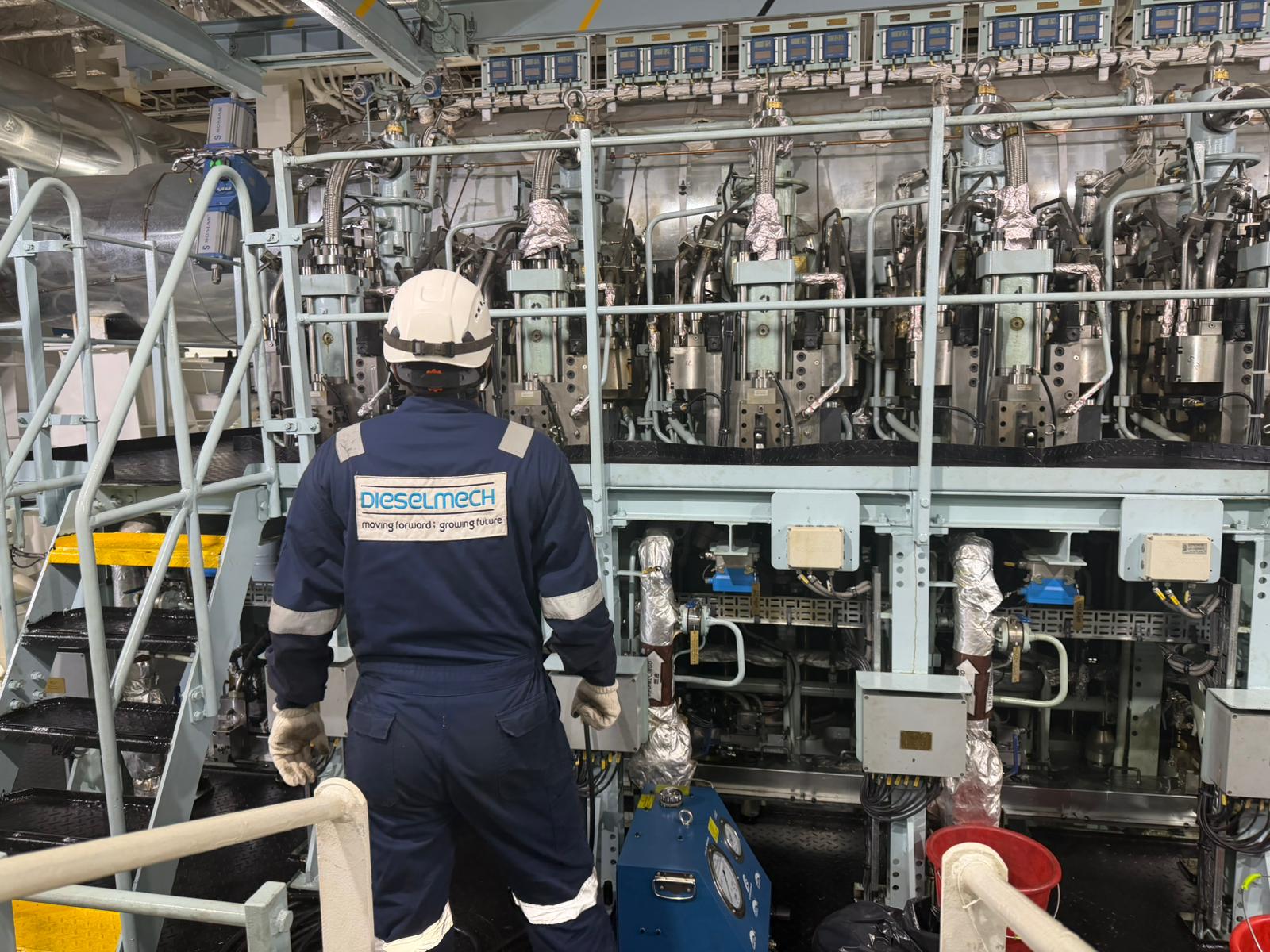
A MAN B&W main engine overhaul is a controlled technical process used to confirm the condition of critical running, sealing, combustion, bearing, injection, lubrication and control components on a large low-speed two-stroke marine diesel engine. The work may involve one cylinder unit, several units, selected bearings, an exhaust-valve programme, fuel equipment, scavenge inspection, cylinder lubrication checks, crankshaft deflection measurement, or a wider marine main engine overhaul scope.
The exact scope is never identical for every MAN B&W engine. It depends on engine type and frame size, MC or MC-C mechanical configuration, ME or ME-C electronically controlled configuration, running hours, condition-monitoring results, previous overhaul records, cylinder performance, class or vessel requirements, maker service letters, available spares, and defects found during dismantling. The aim is to decide what can be reused, what requires reconditioning, what must be renewed, and what needs continued monitoring.
Pre-overhaul assessment and planning
Effective overhaul work starts before the engine is opened. Engineers should identify the exact engine model, serial number, bore size, stroke, control generation and cylinder-unit arrangement, then confirm whether the work applies to an MC/MC-C or ME/ME-C engine. This matters because fuel injection, exhaust-valve control, hydraulic actuation, cylinder lubrication and diagnostic evidence are not the same across all MAN B&W engines.
Planning should review running hours, maintenance history, previous measurement sheets, outstanding defects, recent repairs, alarm or event history, indicator diagrams where available, exhaust-gas temperature trends, cylinder balance, scavenge inspections, cylinder drain-oil condition or analysis, bearing-temperature trends, lubricating-oil condition, abnormal noise, vibration and recent operating restrictions. A good pre-overhaul review helps engineers avoid treating the overhaul as a parts-changing exercise.
Spare-parts availability, specialist tooling, lifting tools, calibrated measuring equipment, hydraulic tools, clean storage, manpower, working time, risk assessment, vessel schedule and class attendance should be confirmed before dismantling. Delays often occur because required sealing parts, piston rings, bearing shells, exhaust-valve parts, fuel-valve spares, hydraulic components, gaskets, locking devices or maker-specific tools were not prepared early enough.
Preparation, safety and controlled isolation
Before dismantling, the engine must be shut down, cooled and isolated according to the vessel's safety management system, maker instructions and approved risk assessments. Actual isolation procedures must be carried out by authorised personnel and verified locally. Typical considerations include starting-air isolation, fuel isolation, turning-gear engagement, electrical isolation, hydraulic isolation where applicable, jacket-water and cooling-water condition, stored-energy hazards, crankcase precautions, lifting arrangements and hot-surface hazards.
Cleanliness and component identification should be treated as part of the technical work. Components should be marked, protected and stored so they can be returned to the correct unit or assessed against the correct measurement record. Dirt, mixed parts, unprotected sealing faces or poor lifting control can create faults that were not present before the overhaul.
Controlled dismantling and inspection sequence
A MAN B&W engine overhaul normally follows a controlled sequence so that parts are removed without damage and findings can be recorded while evidence is still visible. The sequence may include cylinder cover equipment, exhaust valve, fuel valve or injector, starting-air valve, relief or safety valve, piston withdrawal, piston rings, piston rod, stuffing box, cylinder liner inspection, scavenge-space inspection, crosshead checks, guide shoes, crankpin bearing, connecting rod, main bearings, thrust bearing where applicable, crankshaft checks, cylinder lubrication equipment and control or safety devices.
Engineers should avoid cleaning away important evidence before initial inspection. Carbon pattern, blow-by marks, oil wetness, fretting, local overheating, polishing, corrosion, deposits, scuffing, abnormal contact and leakage traces often help explain the running symptom that led to the overhaul.
| Component | Function | Inspection focus | Possible corrective action |
|---|---|---|---|
| Cylinder cover | Forms the combustion-space top closure and carries fitted valves and sealing areas. | Combustion-side condition, sealing faces, cooling passages, studs and nuts, valve seating areas, signs of overheating, erosion, leakage or cracking where suspected. | Cleaning, seating-face assessment, cooling-space cleaning, replacement of seals, NDT where required, specialist repair or renewal. |
| Piston assembly | Transfers combustion force and supports ring sealing. | Crown burning, erosion, deposits, cracks where suspected, cooling spaces where fitted, skirt condition, ring grooves, ring freedom and piston-rod connection. | Cleaning, ring renewal assessment, groove measurement, crown repair where permitted, further inspection or renewal. |
| Cylinder liner | Provides running surface and combustion sealing path for piston rings. | Scoring, scuffing, polishing, corrosion, wear profile, lubrication pattern, port condition, bore wear, ovality and taper. | Honing assessment, cleaning, measurement trending, further specialist inspection or renewal according to maker criteria. |
| Exhaust valve | Controls exhaust-gas release and protects cylinder performance. | Spindle and seat burning, erosion, guide condition, sealing, deposits, actuator, rotation mechanism where fitted, air spring where applicable and leakage evidence. | Cleaning, lapping or machining where permitted, seat/spindle repair, guide attention, actuator service, leak/function test or renewal. |
| Fuel equipment | Delivers fuel quantity, atomisation and timing according to engine type. | Nozzle condition, leakage, deposits, spray/function test, calibration, pump or actuator condition and control evidence. | Fuel injector testing, calibration, overhaul, pump work, ME/ME-C hydraulic or electronic checks where applicable. |
| Bearings and crankshaft | Support running loads and maintain alignment and oil-film condition. | Bearing shell wiping, fatigue, scoring, embedment, journal condition, clearances, lubrication passages, deflection readings where required. | Cleaning, measurement, bearing renewal assessment, journal inspection, oil-system checks, crankshaft deflection trend review. |
Piston overhaul and piston withdrawal
MAN B&W piston overhaul usually includes controlled piston withdrawal, initial visual inspection, cleaning, ring removal, ring groove inspection, piston crown inspection, skirt inspection and piston rod connection checks. Engineers should record the condition before cleaning, because crown deposits, burning marks, blow-by, ring sticking and lubrication pattern often explain cylinder performance problems.
The piston crown should be assessed for burning, erosion, local overheating, abnormal deposits, cracks where suspected and cooling-space condition where applicable. The piston skirt should be checked for scuffing, polishing, seizure marks, scoring and abnormal contact. Piston-ring grooves should be inspected for wear, carbon packing, broken ring marks, burrs and loss of correct ring movement.
Findings should be compared with previous overhaul reports and measurement records. A piston that appears acceptable in isolation may show a worsening trend when compared against previous photographs, ring wear records, liner wear and drain-oil findings.
Cylinder liner inspection and wear measurement
Cylinder liner inspection is one of the most important parts of a MAN B&W main engine overhaul. Engineers inspect for scoring, scuffing, polishing, corrosion, abnormal wear, port-edge condition, surface finish, lubrication pattern, honing condition and evidence of blow-by or poor combustion. The visible surface should be considered together with ring condition and cylinder drain-oil findings where available.
Cylinder liner wear measurement should be taken at maker-specified measuring positions and directions. Measurements are normally arranged so engineers can assess the wear profile down the liner, maximum wear, ovality, taper and any uneven pattern. The measuring tool should be suitable, calibrated and used consistently. Component temperature, cleanliness, measuring direction and recording format matter because small differences can affect trend comparison.
Repeated cylinder liner measurements are valuable because they show whether wear is normal and progressive or sudden and uneven. Liner ovality, liner taper and surface condition should not be interpreted as isolated numbers. They should be compared with piston ring condition, cylinder lubrication, fuel quality, combustion data, exhaust temperature, scavenge condition and previous measurement history. Universal wear limits should not be invented; applicable limits must come from the relevant maker documentation for the exact engine.
Piston ring and ring-groove measurement
Piston ring inspection covers ring wear, breakage, sticking, freedom in the groove, deposits, surface condition, end condition and evidence of blow-by. Ring-groove inspection covers groove wear, carbon packing, burrs, vertical or axial clearance where specified, groove side condition and whether the ring can move correctly under operating conditions.
Excessive piston-ring or ring-groove wear can reduce sealing, increase blow-by, worsen liner lubrication, raise cylinder-oil consumption, increase deposit formation and accelerate liner wear. Ring breakage or sticking may also create liner scoring or abnormal exhaust-gas temperature. Maker-specified checks and acceptance criteria must be used; generic clearance values should not be applied across different engines.
Piston rod and stuffing-box inspection
The piston rod should be inspected where it passes through sealing and scraping areas. Engineers look for scoring, wear, corrosion, surface defects, overheating marks, oil leakage evidence and condition of sealing contact areas. A damaged piston-rod surface can affect crankcase oil contamination, drain condition and stuffing-box performance.
Stuffing-box inspection covers sealing rings, scraper rings, springs, drains, clearances or checks specified by the maker, carbon packing, wear marks and correct assembly. Abnormal drain condition may point to sealing problems, cylinder lubrication issues, ring blow-by, worn scrapers or piston-rod surface damage.
Cylinder cover and fitted valve equipment
The cylinder cover should be assessed on the combustion side, cooling side and sealing faces. Inspection includes combustion deposits, burning marks, sealing-surface condition, cooling passages, studs and nuts, fuel-valve seating areas, starting-air valve arrangement, relief or safety valve condition and other fitted equipment. Crack detection or other NDT should be used where required by maker procedure, condition, overhaul scope or class requirement.
Starting-air valves and cylinder relief or safety valves should be checked for correct condition, cleanliness, seating, leakage evidence and operation according to the applicable engine procedure. Defects in these components can affect starting reliability, safety protection and cylinder condition.
Exhaust valve overhaul
Exhaust valve overhaul should cover spindle and seat condition, burning, erosion, deposits, valve guide condition, sealing surfaces, actuator condition, air-spring arrangement where applicable, rotation mechanism where applicable, leakage and relevant dimensional or function checks. A leaking exhaust valve may appear as high exhaust-gas temperature, low compression, poor combustion, slow starting, power imbalance or abnormal deposits.
Typical reconditioning processes include cleaning, seat and spindle assessment, lapping or machining where permitted, guide assessment, actuator service, air-spring checks and specialist repair according to maker requirements. Engineers should avoid assuming that every exhaust valve can be restored by lapping; seat recession, burning, cracks, excessive guide wear or actuator faults may require further repair or renewal.
Fuel injection and control equipment
Fuel-injection equipment must be treated according to the exact MAN B&W engine configuration. MC and MC-C engines use conventional mechanically timed arrangements with camshaft, roller gear, fuel pumps, linkage and timing-related checks. ME and ME-C engines use electronically controlled and hydraulically actuated arrangements, so the inspection may include control signals, hydraulic actuation, HPS/HCU condition, FIVA or ELFI/ELVA arrangements where applicable, sensors, wiring, feedback and maker diagnostic evidence.
Fuel valves or injectors should be inspected for nozzle condition, deposits, leakage, spray quality, opening or functional behaviour and calibration according to the applicable engine specification. Fuel pumps and electronically controlled injection equipment should not be treated as interchangeable systems. Incorrectly applying MC-C assumptions to an ME-C engine, or ME-C diagnostic logic to an MC-C engine, can lead to wrong conclusions.
Crosshead, crankpin and connecting-rod inspection
Crosshead inspection covers the crosshead pin surface, bearing shell condition, wiping, fatigue, scoring, embedment, contact pattern, lubrication passages, relevant clearances and guide-shoe condition. Guide shoes should be assessed for contact, wear, scoring, lubrication and alignment evidence where applicable. Abnormal crosshead bearing findings can point to lubrication problems, overload, contamination, alignment issues, incorrect assembly or operation outside normal conditions.
Crankpin and connecting-rod inspection includes crankpin journal surface, bearing shells, lubrication condition, relevant bearing clearance, fastening arrangements, fretting evidence and abnormal wear or damage. Bearing shells should be inspected before cleaning removes contact evidence. Any bearing distress should be considered together with oil condition, filter findings, bearing-temperature trends, crankshaft condition and previous measurements.
Main bearings, crankshaft and thrust bearing
Main bearing inspection covers shell condition, wiping, fatigue, scoring, corrosion, embedment, crush or seating evidence, journal surface condition, lubrication passages and bearing clearance according to maker procedure. The crankshaft should be inspected for journal condition, surface marks, overheating evidence, abnormal wear and other maker-specified checks. Thrust bearing inspection, where included in scope, should cover thrust pads or segments, contact pattern, lubrication condition, wear evidence and alignment-related observations.
Crankshaft deflection measurement may be required to assess crankshaft alignment and structural condition. The value of crankshaft deflection readings depends on consistent measurement conditions, correct turning positions, suitable measuring equipment, comparable vessel condition and comparison with previous records. Universal acceptance values should not be used; the applicable engine manual, vessel records and class requirements must be followed.
Scavenge space and cylinder lubrication inspection
Scavenge-space inspection should cover deposits, oil accumulation, drain condition, scavenge-port observations, piston underside condition, visible liner condition, traces of blow-by, scavenge-fire damage, abnormal combustion deposits and evidence of poor cylinder lubrication. Scavenge findings often help explain high exhaust-gas temperature, black smoke, abnormal drain oil, piston-ring problems and liner wear.
Cylinder lubrication inspection should cover lubricator condition, feed arrangements, oil distribution, pipework, non-return devices where fitted, delivery evidence and correct system behaviour. Electronically controlled cylinder lubrication systems should be distinguished from conventional arrangements. On ME/ME-C engines, lubrication evidence may need to be considered together with control settings and operating profile.
ME-C and MC-C configuration-specific checks
Common mechanical overhaul work is shared across MAN B&W engine families: piston overhaul, liner measurement, ring inspection, exhaust valve overhaul, bearing inspection, crankshaft checks, scavenge inspection and reporting remain essential. The configuration-specific work is different. MC and MC-C engines require closer attention to camshaft condition, roller guides, fuel-pump timing, pump condition, mechanical linkages and cam-driven actuation.
ME and ME-C engines may require inspection of electronic and hydraulic control equipment, including Hydraulic Power Supply, Hydraulic Cylinder Unit, FIVA or ELFI/ELVA arrangements where applicable, sensors, control units, hydraulic oil cleanliness, wiring, connectors, feedback and diagnostic records. These checks must follow the specific engine generation and control-system documentation.
Key main engine overhaul measurements
Main engine overhaul measurements should be recorded consistently and compared with previous records. Measurements are normally taken at specified positions because wear is not uniform. Tool calibration, component cleanliness, temperature, measuring direction, repeatability and clear recording are important. Numerical limits must come from the engine-specific instruction book, maintenance manual, service bulletins and class or vessel requirements.
| Component | Measurement/Check | What engineers assess | Possible significance of abnormal findings |
|---|---|---|---|
| Cylinder liner | Bore, wear profile, ovality, taper and surface condition | Whether liner wear is even, progressive and within maker criteria. | Abnormal lubrication, corrosion, abrasive wear, scuffing, ring trouble or poor combustion. |
| Piston rings | Ring wear, freedom, breakage, sticking and condition | Sealing ability and ring movement. | Blow-by, high cylinder-oil use, liner scoring, poor compression or deposit formation. |
| Ring grooves | Groove condition and maker-specified clearance checks | Whether rings can seal and move correctly. | Excessive groove wear, carbon packing, ring flutter, blow-by or accelerated liner wear. |
| Piston rod | Sealing surface condition and wear/scoring checks | Condition of stuffing-box contact area. | Oil leakage, crankcase contamination, scraper-ring wear or sealing failure. |
| Stuffing box | Sealing rings, scraper rings, springs, drains and clearances | Ability to separate cylinder and crankcase spaces. | Abnormal drain condition, oil contamination, leakage or worn sealing elements. |
| Cylinder cover | Sealing faces, combustion face, cooling passages and fitted valves | Structural, sealing and cooling condition. | Leakage, overheating, erosion, deposits, cracked areas where suspected or valve seating issues. |
| Exhaust valve | Spindle, seat, guide, leakage and actuator/function checks | Sealing, movement and thermal condition. | High exhaust temperature, low compression, leakage, poor combustion or actuator problem. |
| Fuel injector/fuel valve | Nozzle condition, leakage, function/spray and calibration checks | Fuel atomisation and delivery condition. | Poor combustion, black smoke, abnormal exhaust temperature or cylinder imbalance. |
| Crosshead bearing | Bearing shell condition, contact pattern and clearance | Load carrying condition and oil-film evidence. | Lubrication failure, overload, contamination, misalignment or bearing distress. |
| Guide shoes | Contact, wear and clearance where applicable | Guiding and alignment condition. | Uneven load, lubrication issue, alignment concern or abnormal mechanical contact. |
| Crankpin bearing | Shell condition, clearance, journal surface and lubrication | Bearing load condition and crankpin health. | Wiping, fatigue, scoring, oil starvation, contamination or overload. |
| Main bearing | Shell condition, clearance, journal surface and oil passages | Crankshaft support condition. | Misalignment, oil-film problem, contamination, bearing fatigue or journal damage. |
| Crankshaft | Journal condition and deflection readings where required | Surface condition and alignment trend. | Alignment change, bearing issue, hull/loading influence or structural concern requiring further assessment. |
| Thrust bearing | Pad/segment condition, contact and lubrication where applicable | Axial-load carrying condition. | Poor contact, lubrication distress, wear or alignment-related issue. |
| Control equipment | ME/ME-C hydraulic/electronic checks or MC/MC-C timing checks | Correct response of configuration-specific equipment. | Command/feedback mismatch, hydraulic pressure issue, sensor fault, timing fault or mechanical actuation problem. |
Measurement interpretation and trending
Measurement interpretation should distinguish normal progressive wear from sudden change, uneven wear or symptoms that do not match the recorded values. A single measurement rarely tells the whole story. Cylinder liner wear, liner surface condition, piston-ring condition, bearing clearances, crankshaft deflection, exhaust-valve condition, fuel-injection behaviour and combustion data should be considered together.
Trending is especially useful for cylinder liner wear measurement, bearing clearances, crankshaft deflection measurement and repeated exhaust-valve findings. A value that is still acceptable may still require attention if the change since the last overhaul is unusually rapid or uneven. Conversely, a component may look worn but still require confirmation by measurement and maker criteria before renewal decisions are made.
Symptom, possible cause and inspection
| Symptom | Possible cause | Inspection |
|---|---|---|
| High exhaust-gas temperature | Exhaust-valve leakage, injector fault, low compression, poor combustion, scavenge restriction or overload | Compare exhaust trends, indicator data where available, valve condition, injector function, compression evidence and scavenge condition |
| Cylinder imbalance | Fuel delivery issue, compression loss, liner/ring condition, exhaust leakage, ME-C control issue or MC-C timing problem | Compare cylinder data, fuel equipment, liner/rings, exhaust valve, control alarms and timing evidence |
| Low compression | Ring wear/sticking, liner wear, exhaust-valve leakage, cover leakage or piston condition | Inspect piston rings, liner, exhaust valve, cover sealing and indicator/compression evidence where available |
| Abnormal peak pressure | Injection timing/quantity issue, combustion condition, compression difference or control/timing fault | Review indicator diagrams, fuel equipment, MC-C timing or ME-C command/control data |
| Excessive cylinder-oil consumption | Lubrication setting/condition, liner wear, ring wear, blow-by or drain issues | Check cylinder-oil records, liner surface, ring condition, scavenge deposits and drain-oil findings |
| Abnormal liner wear | Lubrication issue, corrosion, abrasive particles, fuel quality, ring trouble or poor running-in | Measure liner wear/ovality/taper, inspect rings, drain oil, lubrication equipment and combustion condition |
| Liner scoring or scuffing | Oil-film failure, broken ring, contamination, overload, poor lubrication or thermal distress | Inspect liner surface, rings, piston skirt, lubrication evidence and recent operating history |
| Piston-ring breakage or sticking | Deposits, groove wear, poor lubrication, overload, liner condition or incorrect ring movement | Inspect rings, grooves, liner, scavenge space and drain-oil evidence |
| Blow-by | Poor ring sealing, liner wear, ring sticking, groove wear or piston damage | Inspect piston rings, ring grooves, liner wear profile, piston crown/skirt and scavenge evidence |
| Exhaust-valve leakage | Burnt seat/spindle, deposits, guide wear, actuator issue or poor seating | Leak/function checks, inspect spindle, seat, guide, actuator and temperature trend |
| Injector malfunction | Nozzle deposit, leakage, poor spray, calibration issue or fuel contamination | Function/spray test, inspect nozzle, leakage, filter/fuel condition and cylinder trend |
| Black smoke or poor combustion | Poor atomisation, insufficient air, overload, low compression, timing/control issue or fuel quality | Check fuel injectors, air path, compression evidence, turbo/scavenge condition and control/timing data |
| Increased bearing temperature | Lubrication issue, bearing clearance/contact problem, contamination, overload or alignment concern | Inspect bearing shell, oil supply, temperature trend, journal condition and clearance |
| Abnormal bearing wear | Oil contamination, poor lubrication, misalignment, overload, fatigue or assembly issue | Inspect shell, journal, oil passages, filters, clearances and deflection records |
| Crankcase abnormalities | Bearing distress, oil mist concern, contamination, overheating or mechanical contact | Follow vessel safety procedure, inspect oil condition, bearing areas, temperature trend and alarm history |
| Abnormal noise or vibration | Bearing issue, crosshead/guide shoe wear, combustion knock, loose component or mechanical contact | Localise noise, review trends, inspect bearings, crosshead, guide shoes, piston assembly and combustion data |
| Scavenge deposits | Blow-by, poor combustion, excessive oil, ring trouble or poor air path | Inspect scavenge space, piston underside, rings, liner surface, drain condition and exhaust trend |
| Abnormal drain-oil findings | Wear particles, contamination, poor lubrication, corrosion or abnormal cylinder condition | Review drain-oil analysis where used, inspect liner, rings, piston, stuffing box and lubrication system |
Reuse, reconditioning or renewal decision
The decision to reuse, recondition or renew a component should be based on measured condition, visual findings, NDT where applicable, maker criteria, service history, running symptoms and engineering judgement. It should not be based on arbitrary universal limits. Components may be reused if condition and measurements are acceptable for the specific engine and service plan. They may require reconditioning if repair is permitted by maker procedure and can restore the component to acceptable condition. Renewal is required when wear, damage, cracking, distortion, excessive clearance, poor sealing, fatigue or other findings exceed acceptable criteria or create unacceptable risk.
Reassembly and final verification
Reassembly should begin only after components have been cleaned, inspected, measured and accepted for installation. Required seals, O-rings, gaskets, locking devices and single-use parts should be renewed according to maker requirements. Component identification, orientation and unit allocation should be confirmed before fitting. Critical parts should be lubricated, protected from contamination and installed using correct tools and lifting methods.
Controlled tightening, hydraulic tool use, clearances, timing, adjustment, free-movement checks and independent verification of critical work should follow maker-specified procedures. On MC/MC-C engines this may include mechanical timing and fuel-pump related checks. On ME/ME-C engines it may include hydraulic/control function checks and verification of sensors or feedback where applicable.
Post-overhaul testing and commissioning
Post-overhaul testing should confirm that the engine can be safely turned, started and loaded without abnormal findings. Typical checks include turning gear checks, freedom of movement, leak checks, starting checks, alarm and safety-device verification where required, fuel and lubrication checks, cooling-water checks, hydraulic/control-system behaviour where applicable, and observation for abnormal noise, vibration or leakage.
Load-up should be gradual and monitored. Engineers should watch bearing temperatures, exhaust-gas temperatures, cylinder balance, combustion performance, cylinder lubrication, cooling-water condition, crankcase condition, scavenge condition and relevant ME/ME-C hydraulic or control behaviour. Post-overhaul performance should be compared with pre-overhaul and historical data where available.
Final overhaul documentation
A complete MAN B&W engine overhaul report should include engine identification, running hours, overhaul scope, dismantling findings, photographs, measurement sheets, before and after condition where relevant, parts renewed, components reconditioned, calibration or testing performed, post-overhaul test results, outstanding observations and recommendations for future inspection or monitoring.
Good documentation allows future engineers to understand whether wear is progressive, sudden, repeated or connected to operating conditions. It also supports ship managers, technical superintendents, vessel owners and class or survey planning when deciding the next maintenance scope.
FAQ
What is included in a MAN B&W main engine overhaul?
The scope may include piston withdrawal, piston and ring inspection, cylinder liner measurement, cylinder cover inspection, exhaust valve overhaul, fuel injector testing, stuffing-box inspection, scavenge inspection, bearing checks, crankshaft deflection measurement, reassembly, testing and documentation. The exact scope depends on engine type, condition, history and maker requirements.
How often is a MAN B&W main engine overhauled?
Overhaul interval is engine-specific. It depends on the engine model, running hours, fuel, operating profile, condition monitoring, maker recommendations, class requirements and previous findings. Universal overhaul intervals should not be applied without the relevant instruction book and vessel maintenance plan.
What measurements are taken during piston withdrawal?
Typical checks may include piston crown and skirt condition, piston-ring condition, ring-groove condition and clearances where specified, piston rod sealing surface, stuffing-box condition, cylinder liner bore, liner wear, ovality and taper, plus related maker-specified inspections.
How is cylinder-liner wear measured?
Cylinder liner wear is measured using suitable calibrated equipment at maker-specified positions and directions. The purpose is to record wear profile, maximum wear, ovality, taper and surface condition, then compare the results with engine-specific limits and previous records.
What are liner ovality and taper?
Ovality describes the difference in liner bore measurement between directions at a measuring level. Taper describes change in bore measurement along the liner height. Both help engineers understand whether wear is even, progressive or abnormal.
Why are piston-ring grooves measured?
Piston-ring grooves are measured because excessive groove wear, carbon packing or incorrect clearance can prevent rings from sealing and moving correctly. This can contribute to blow-by, liner wear, oil consumption and poor combustion.
What is checked on a crosshead bearing?
Engineers inspect bearing shell condition, crosshead pin surface, contact pattern, wiping, fatigue, scoring, lubrication passages and maker-specified clearances. Guide-shoe condition may also be checked where applicable.
Why is crankshaft deflection measured?
Crankshaft deflection readings help assess crankshaft alignment and changes in support condition. Readings must be taken consistently and compared with previous records, maker guidance and class requirements rather than generic values.
What is inspected on an exhaust valve?
Exhaust valve inspection includes spindle and seat condition, burning, erosion, guide condition, leakage, deposits, actuator condition, air spring where applicable, rotation mechanism where applicable and function checks according to engine procedure.
What is checked after a main engine overhaul?
Post-overhaul checks include turning, leak checks, starting, gradual load-up, bearing temperature, exhaust temperature, cylinder balance, lubrication, cooling water, abnormal noise or vibration, safety checks where required and comparison against previous performance.
Are ME-C and MC-C overhaul procedures the same?
They share many mechanical overhaul tasks, but they are not identical. MC/MC-C engines require mechanical timing, camshaft, roller and fuel-pump checks. ME/ME-C engines may require hydraulic, electronic, sensor, HPS, HCU, FIVA or ELFI/ELVA checks depending on engine generation and configuration.
Measurements and acceptance limits
Condition assessment should be based on recorded measurements, visual findings, operating symptoms, and the applicable maker documentation. Acceptable limits should be confirmed against the applicable manufacturer's manual and engine-specific technical documentation.
Need technical assistance?
If inspection, overhaul, troubleshooting, workshop repair, or onboard attendance is required, Dieselmech Group can review the symptoms, engine details, operating history, and available measurements before recommending the next practical step. Contact us at +65 6334 1855, email sales@dieselmech.com.sg, or submit an enquiry through the Contact Us page.
Technical note
This article is for general technical information. Actual procedures, limits, clearances, pressures, temperatures, torque values, and renewal criteria depend on the engine model, configuration, maker revision, service bulletin, vessel procedures, and class requirements. Manufacturer manuals and vessel safety procedures take precedence. Safety-critical work should be carried out by appropriately qualified personnel.
Published by Dieselmech Group Technical Team. For advice on a specific engine or fault, contact our marine engineers.